Snake plunger

Inactive Publication Date: 2005-05-31
GEORGE TASH & DEBRA B TASH AS TRUSTEES OF THE COMMUNITY TRUST CREATED UNDER THE GEORGE TASH & DEBRA B TASH INTER VIVOS TRUST AGREEMENT DATED NOVEMBER 25 1985 AS AMENDED & TOTALLY RESTATED ON MAY 19 1999
View PDF32 Cites 34 Cited by
  • Summary
  • Abstract
  • Description
  • Claims
  • Application Information

AI Technical Summary

Benefits of technology

[0010]A “snake plunger” according to present invention satisfies all of the foregoing needs. The snake plunger is adapted for use with a variety of sizes and shapes of drain openings such as are common in toilets, sinks, tubs, etc. The design of the plunger embodied in the present invention is such that the problems of drain blockage, slippage, splashing, spillage, splash back, and spillover are lessened or eliminated. Furthermore, the plunger can be easily and inexpensively molded, preferably of durable rubber or plastic. The plunger is also lightweight and easy to use.
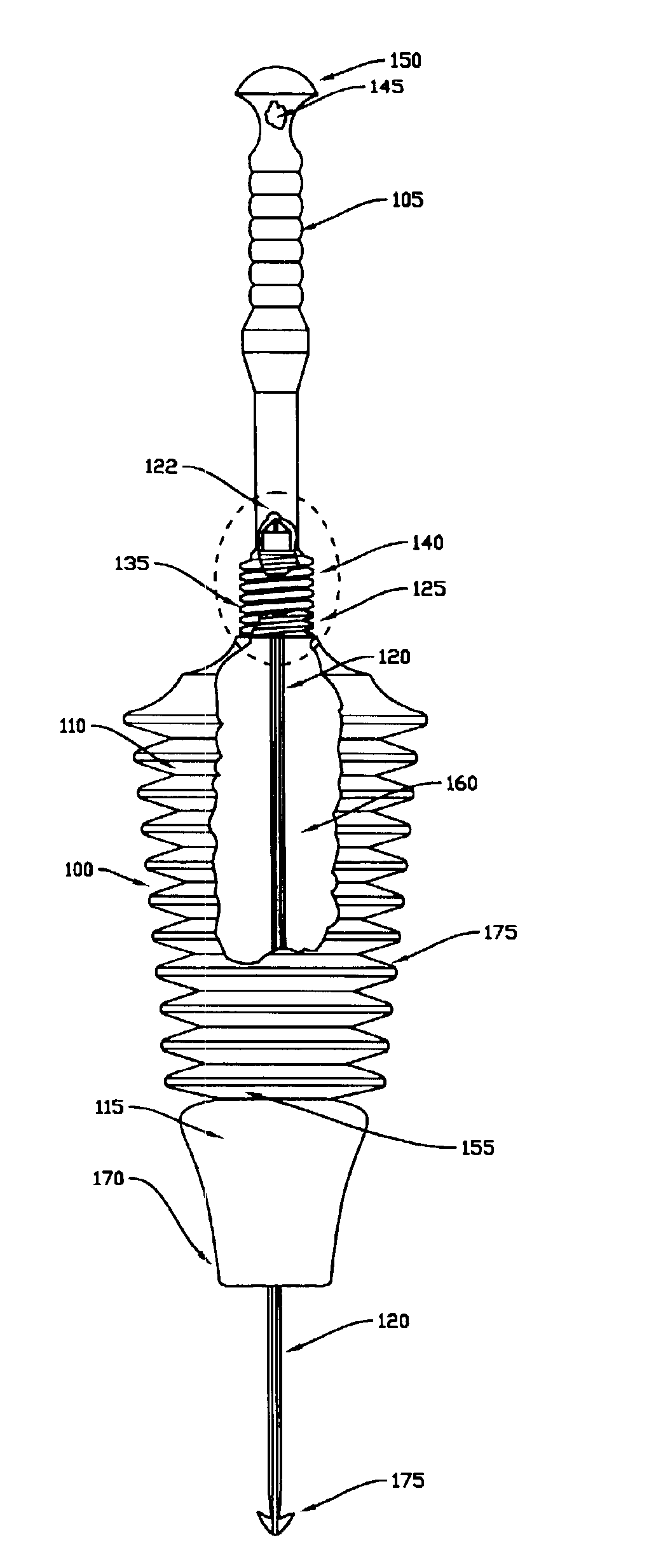
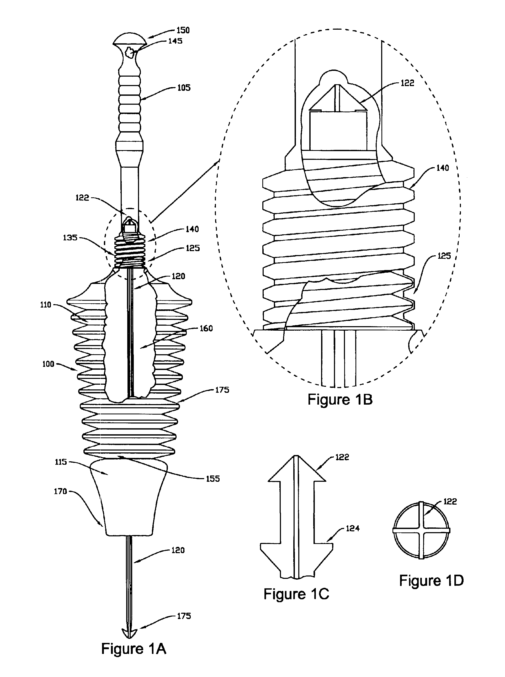
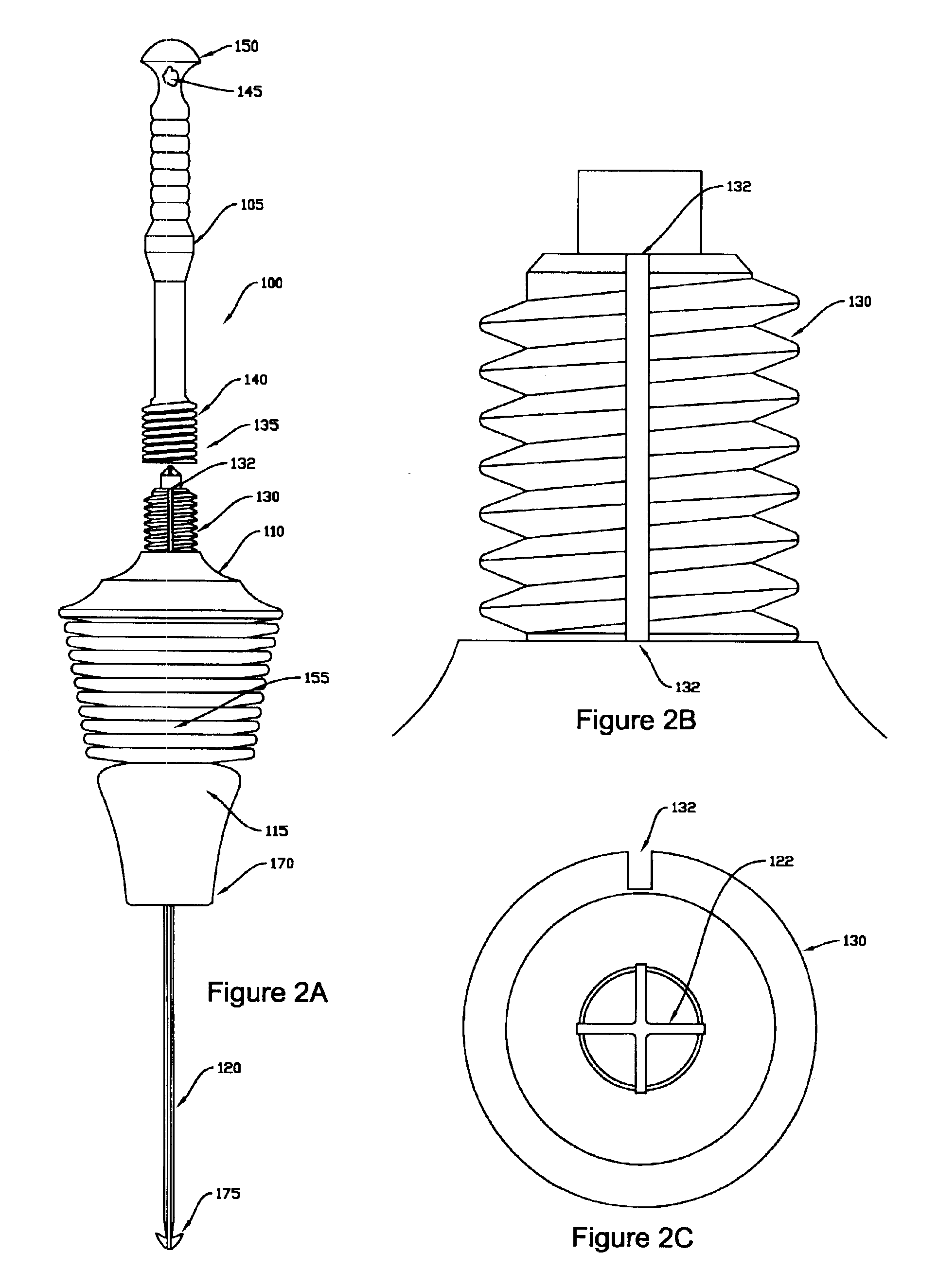
[0011]In general, a plunger according to present invention consists of an elongated handle attached to the upper end of an elongated “head” section, a seal section which is attached to the lower end of the head section, and a flexible internal “snake” which extends through the interior of the head, and is attached to the interior of the top of the head section. In alternate embodiments, the handle is either permanently or releasable attached to the head section. In one embodiment, the head section of the plunger is a pleated bellows which is generally conical and of decreasing diameter from top to bottom. Further, because the head section decreases in diameter towards the bottom of the head, displacement of wastewater from within the basin is minimized.
[0012]In operation, the snake plunger is placed into position above a clogged drain. Next, as pressure is applied downward on the handle, the bellows forming the head section compresses, and the portion of the seal in contact with the drain opening forms a mechanical and / or a pressure / suction seal with the drain opening, depending upon the size of the drain opening. Consequently, the pressure generated by compression of the bellows is directed through the sealing structures and into the drain in the direction of the obstruction. Further, at the same time, the snake extends through the seal section and into the drain during compression of the bellows. Next, as the handle is then pulled upwards, a suction force is applied to the obstruction in the drain. These reciprocating forces, in conjunction with the movement of the snake into and out of the drain effectively and rapidly dislodges obstructions from within the drain, thereby facilitating rapid clearing of the drain.
[0013]In an alternate embodiment, the handle and head section are jointly configured to release air from within the head section by loosening the handle slightly when inserting the head of the plunger into a basin filled with wastewater. This release of air from the head serves to simultaneously allow wastewater into the head so as to avoid the problem of spillover. Tightening the handle then serves to prevent the flow of air from within the head. In a related embodiment, a one-way bleed valve or the like is included in either the head or handle for releasing air from within the bellows for minimizing displacement of wastewater when inserting the head of the plunger into a basin filled with wastewater.
[0014]The bottom end of the plunger consists of a seal section that depends from the bottom of the bellows. A seal located at the bottom of the seal section is designed to either seat securely within a typical drain opening, or alternately, in the case where the drain opening is smaller in diameter than the seal, to form a pressure seal around the smaller drain opening. This seal is capable of forming either or both a mechanical and pressure seal with the drain hole being cleared by the plunger, depending upon the diameter of the drain opening. The seal improves the pressure and suction forces applied by the plunger while serving to limit or prevent the lateral slippage that is responsible for splashing and / or splash back of wastewater from within the basin. Further, a flat bottom end of the seal section allows the plunger to form a pressure seal with the surface surrounding a smaller drain opening. In addition, alternate seal designs and shapes are used in various embodiments to adapt the snake plunger to better interface with various sizes, shapes, and styles of drain openings.
[0016]In related embodiments, compression of the bellows is used to direct compressed air from within the bellows and into the snake. In these related embodiments, the compressed air entering the snake is then used to extend the snake further into the drain, or alternatively, to assist in clearing blockages within the drain by venting compressed air through the end of the snake and thus into the drain in the direction of the obstruction.

Problems solved by technology

There are various problems associated with plunging a clogged drain.
Some of these problems are related to the drain configuration, while other problems are related to the design of the plunger itself.
A common problem associated with use of existing plungers is that obstructions within a drain may be too compact, or wedged too tightly within the drain, for alternating pressure and suction forces to dislodge such an obstruction.
Further, the bottom end of the plunger cap of typical plunger devices has the tendency to slide about over the surface surrounding the drain opening being cleared.
As a result, splashing and / or spillage of standing wastewater from within the basin above the drain are common.
Another problem associated with conventional plunger devices is the limited volume of the plunger cup.
Consequently, conventional plungers are often unable to provide sufficient pressure or suction to dislodge an obstruction that is blocking the drain.
Another problem typically seen with these cup-type plungers is the tendency for wastewater to spray out with great force from between the plunger cup and the surface surrounding the drain opening.
In addition, existing plungers tend to displace a relatively large quantity of wastewater when the plunger is inserted into the basin above a clogged drain.
Further, because the snake extends into a drain concurrently with the pressure generated during bellows compression, obstructions may be rapidly cleared.

Method used


Image

  • Snake plunger
  • Snake plunger
  • Snake plunger

Examples


Embodiment Construction

[0031]In the following description of the preferred embodiments according to the present invention, reference is made to the accompanying drawings, which form a part hereof, and which are shown by way of illustration of specific embodiments in which the invention may be practiced. It is understood that other embodiments may be utilized and structural changes may be made without departing from the present scope of the invention.

1.0 Overview:

[0032]In general, a “snake plunger,” as described herein, operates to simultaneously plunge and snake clogged drains. In particular, the snake plunger operates by first placing the snake plunger into position above a clogged drain. Next, as pressure is applied downward on a handle of the snake plunger, a compressible pleated head section of the snake plunger compresses, and a portion of a seal in contact with a drain opening forms a mechanical and / or a pressure / suction seal with that drain opening, depending upon the size of the drain opening. Con...


PUM


Abstract

This invention relates to a drain plunger that snakes clogged drains at the same time that the drains are being plunged. The “snake plunger” includes a pleated bellows forming a head section which is removably coupled to a handle. Further, in one embodiment, the head and handle sections are jointly configured to release air from within the bellows while the plunger is being inserted into a basin filled with wastewater, thereby reducing or eliminating potential spillover. Further, a flexible elongated snake disposed within the interior of the bellows enters the drain as the plunger bellows is compressed. The snake is capable of dislodging and breaking up obstructions within a drain. Further, the snake may also have a hook at its lower end that is capable of snaring items causing obstructions within the drain. These features combine to create a plunger that provides a superior ability to effectively clear clogged drains.

Description

BACKGROUND OF THE INVENTION[0001]1. Technical Field[0002]This invention relates to a water and sewage drain plunger for use in clearing clogged drains and drain openings, and in particular, to a drain plunger which is adapted to snake drains and drain openings concurrently with the plunging operation.[0003]2. Background Art[0004]There are various problems associated with plunging a clogged drain. Some of these problems are related to the drain configuration, while other problems are related to the design of the plunger itself.[0005]By way of background, drains such as those in toilets, sinks, and tubs are typically unclogged by using a toilet plunger comprised of a large deformable cup mounted on the end of an elongated handle or shaft. Other plunger designs include a larger air chamber or bellows coupled to a seal. In either case, during the plunging operation, the plunger cup or seal is held over, or inserted into, the mouth of the drain while the plunger handle is reciprocated in...

Claims


Application Information

Patent Timeline
IPC IPC(8): E03C1/308E03C1/12E03C1/302E03D11/00
CPCE03C1/302E03D11/00E03D9/00E03C1/308
Inventor TASH, GEORGE
Owner GEORGE TASH & DEBRA B TASH AS TRUSTEES OF THE COMMUNITY TRUST CREATED UNDER THE GEORGE TASH & DEBRA B TASH INTER VIVOS TRUST AGREEMENT DATED NOVEMBER 25 1985 AS AMENDED & TOTALLY RESTATED ON MAY 19 1999
Why Eureka
Try Eureka