
Micro-electro-mechanical system (MEMS) variable capacitor apparatuses and related methods

a micro-electromechanical system and variable capacitor technology, applied in the field of micro-electromechanical systems (mems) variable capacitor apparatuses, can solve the problems of complex and costly implementation, unsatisfactory noise/interference or degradation of signal on signal lines, variable capacitor types are also subject to microphonics and stiction problems

Inactive Publication Date: 2005-05-24
AAC TECH PTE LTD
View PDF4 Cites 81 Cited by
  • Summary
  • Abstract
  • Description
  • Claims
  • Application Information

AI Technical Summary

Problems solved by technology

One problem with this configuration is that the voltage supply is electrically connected to the signal line through the plate that can result in undesirable noise / interference or degradation of the signal on the signal line.
Thus, this configuration may require additional components to combine / separate the signal and actuation voltage, leading to a more complex and costly implementation.
These types of variable capacitors are also subject to microphonics and stiction problems.
These types of variable capacitors are subject to reduced power handling capability due to gap reduction and the likelihood for breakdown occurrence.
These variable capacitors also consume excessive power, especially if the electro-thermal actuation must be applied continuously to maintain the capacitance value.
Thus, this type of variable capacitor is not readily integrated into a conventional integrated circuit (IC) process.
Additionally, the MEMS device is physically large because the capacitance dependence on the overlap of comb fingers requires large aspect ratios.
These devices require excessive space and cause a low resonant frequency resulting to shock and vibration problems.

Method used


Image

  • Micro-electro-mechanical system (MEMS) variable capacitor apparatuses and related methods
  • Micro-electro-mechanical system (MEMS) variable capacitor apparatuses and related methods
  • Micro-electro-mechanical system (MEMS) variable capacitor apparatuses and related methods

Examples


Embodiment Construction

[0025]It is understood that when a component such as a layer, substrate, contact, interconnect, electrode, conductive plate, or conductive line is referred to herein as being deposited or formed “on” another component, that component can be directly on the other component or, alternatively, intervening components (for example, one or more buffer or transition layers, interlayers, electrodes or contacts) can also be present. Furthermore, it is understood that the terms “disposed on”, “attached to” and “formed on” are used interchangeably to describe how a given component is positioned or situated in relation to another component. Therefore, it will be understood that the terms “disposed on”, “attached to” and “formed on” do not introduce any limitations relating to particular methods of material transport, deposition, or fabrication.

[0026]Contacts, interconnects, electrodes, conductive plates, conductive lines, and other various conductive elements of various metals can be formed by ...


PUM


Abstract

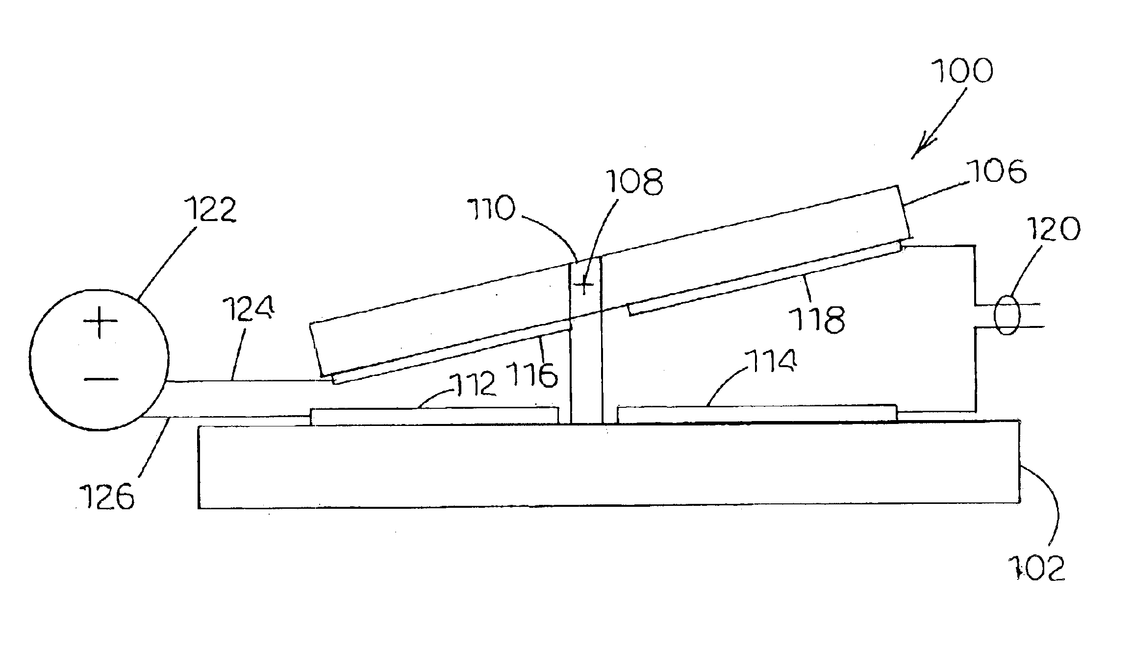
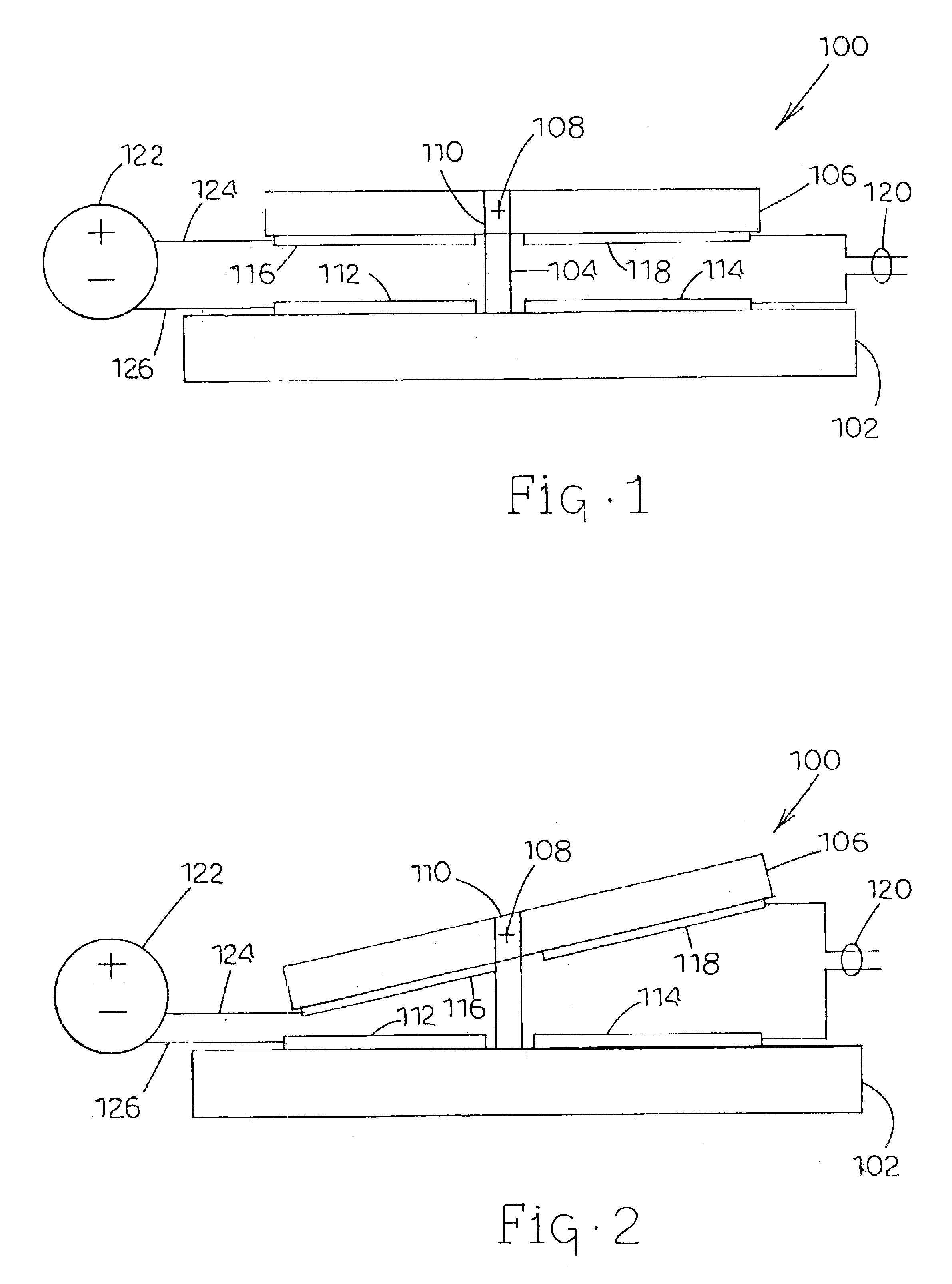
Micro-Electro-Mechanical System (MEMS) Variable Capacitor Apparatus and Related Methods. According to one embodiment, a MEMS variable capacitor is provided. The variable capacitor can include first and second electrodes being spaced apart, and at least one of the electrodes being movable when a voltage is applied across the first and second electrodes. The variable capacitor can also include a first conductive plate attached to and electrically isolated from the first electrode. Furthermore, the variable capacitor can include a second conductive plate attached to the second electrode and spaced from the first conductive plate for movement of at least one of the plates with respect to the other plate upon application of voltage across the first and second electrodes to change the capacitance between the first and second plates.

Description

CROSS-REFERENCE TO RELATED APPLICATION[0001]This nonprovisional application claims the benefit of U.S. Provisional Application No. 60 / 388,490, filed Jun. 13, 2002, the disclosure of which is incorporated by reference herein in its entirety.TECHNICAL FIELD[0002]The present subject matter relates generally to micro-electro-mechanical systems (MEMS) apparatuses and methods. More particularly, the present subject matter relates to variable capacitor apparatuses and related methods utilizing MEMS technology.BACKGROUND ART[0003]Micro-electro-mechanical systems (MEMS) apparatuses and methods are presently being developed for a wide variety of applications in view of the size, cost and power consumption advantages provided by these devices. Specifically, a variable capacitor, also known as a varactor, can be fabricated utilizing MEMS technology. Typically, a variable capacitor includes an interelectrode spacing between a pair of electrodes that can be controllably varied in order to selecti...

Claims


Application Information

Patent Timeline
Patent Type & Authority Patents(United States)
IPC IPC(8): H01L29/76H01L27/14H01L29/66H01L27/108B81B3/00H01G5/18H10B12/00
CPCH01G5/18
Inventor DE LOS SANTOS, HECTOR J.
Owner AAC TECH PTE LTD
Learn More