Eureka AIR delivers breakthrough ideas for toughest innovation challenges, trusted by R&D personnel around the world.

Tube retainer

a retainer and tube technology, applied in the direction of couplings, cycle equipments, rod connections, etc., can solve the problems of over-locking the tube, inability to distribute the stress in the prior art, and defects still exist in the prior ar

Inactive Publication Date: 2005-05-24
CHEN CHAO HU
View PDF3 Cites 37 Cited by
  • Summary
  • Abstract
  • Description
  • Claims
  • Application Information

AI Technical Summary

Benefits of technology

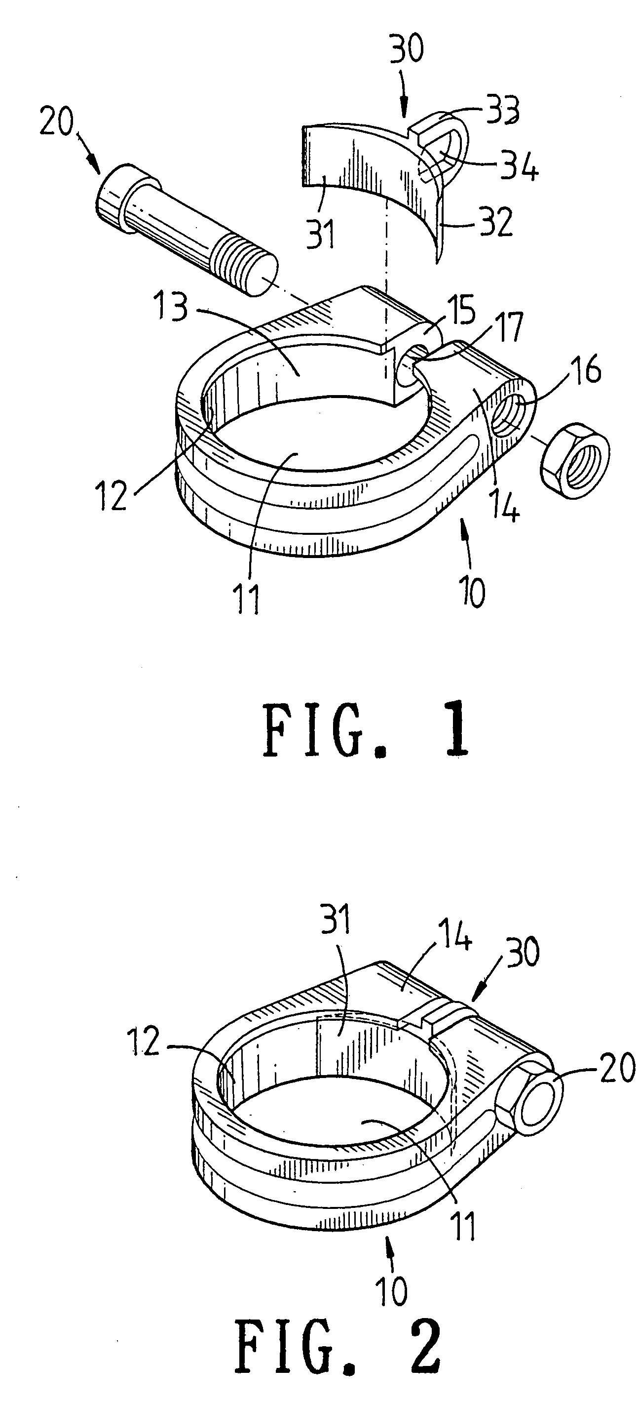
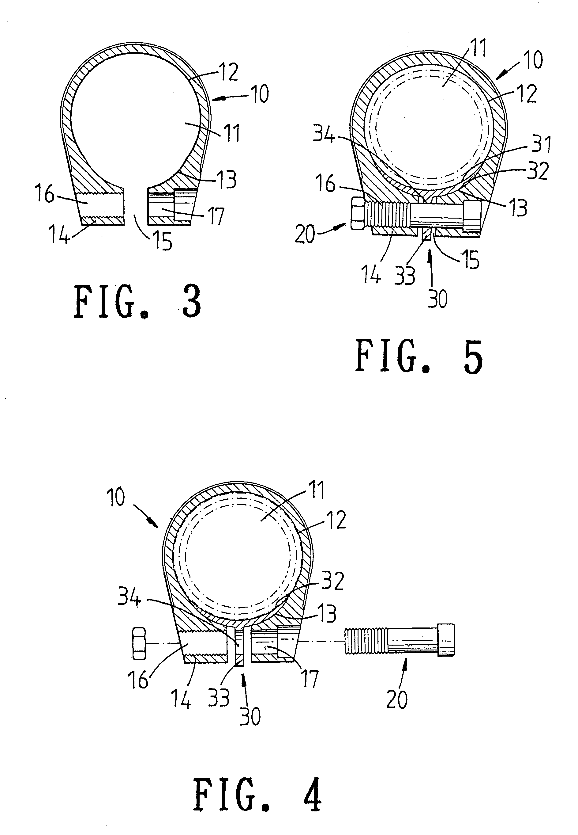
[0006]Accordingly, the primary object of the present invention is to provide a tube retainer which comprises a tube body; a center of the tube body being formed with a receiving space; the receiving space being formed by a large cambered surface and a small cambered surface; one end of the tube body being formed with a tightening portion; the tightening portion being formed with a slot communicated with the receiving space and the outside of the tube body; a hole being formed in the tube body and the hole passing through the slot; a pad having a cambered surface which has the same radian as that of the receiving space; a protrusion protruding from the outer cambered surface; the protrusion having a through hole for retaining the screw fastener.
[0007]Moreover, in the present invention, the receiving space has a large cambered surface and a small cambered surface. A threaded hole is formed in the tightening portion and at one side of the slot and a via hole is formed in the tightening portion and at another side of the slot. The small cambered surface is at the tightening portion and is adhered to the pad.
[0008]The various objects and advantages of the present invention will be more readily understood from the following detailed description when read in conjunction with the appended drawing.

Problems solved by technology

Although this structure has the function of tightening a tube, but the tube retainer will over-lock the tube.
However, this structure still concentrate the stress in the openings of the sleeve and the tightening rings.
Thus, the defects in the prior art still exist.
Thereby, the prior arts cannot make the stress to distributed uniformly.
This is because the space for clamping a tube is not a complete and uniform cycle.

Method used


Image

  • Tube retainer
  • Tube retainer
  • Tube retainer

Examples


Embodiment Construction

[0014]In order that those skilled in the art can further understand the present invention, a description will be described in the following in details. However, these descriptions and the appended drawings are only used to cause those skilled in the art to understand the objects, features, and characteristics of the present invention, but not to be used to confine the scope and spirit of the present invention defined in the appended claims.

[0015]The tube retainer of the present invention is illustrated in FIGS. 1 to 3. The tube retainer includes a tube body 10. A center of the tube body 10 is formed with a receiving space 11. The receiving space 11 is formed by a large cambered surface 13 and a small cambered surface 12 (referring to FIG. 3). One end of the tube body 10 is formed with a tightening portion 14. The tightening portion 14 is formed with a slot 15 communicated with the receiving space 11 and the outside. A threaded hole 16 is formed in the tightening portion 14 and verti...


PUM


Abstract

A tube retainer comprises a tube body; a center of the tube body being formed with a receiving space; the receiving space being formed by a large cambered surface and a small cambered surface; one end of the tube body being formed with a tightening portion; the tightening portion being formed with a slot communicated with the receiving space and the outside of the tube body; a hole being formed in the tube body and the hole passing through the slot; a pad having a cambered surface which has the same radian as that of the receiving space; a protrusion protruding from the outer cambered surface; the protrusion having a through hole for retaining the screw fastener. The receiving space has a large cambered surface and a small cambered surface. A threaded hole is formed in the tightening portion and at one side of the through the slot and a via hole is formed in the tightening portion and at another side of the slot. The small cambered surface is at the tightening portion and is adhered to the pad.

Description

FIELD OF THE INVENTION[0001]The present invention relates to tube retainers, and particular to a tube retainer having an uniform inner space so that stress can be uniformly distributed in the whole inner space and thus no deformation occurs.BACKGROUND OF THE INVENTION[0002]In one prior art of tube retainers, see FIGS. 7 and 8, a shaft is inserted into a sleeve. An outer edge of the sleeve is enclosed by a tube retainer for fixing the shaft in the sleeve. The feature of this prior art is that a buckle is inserted into a hole of the tube retainer. The tube retainer is enclosed in section of the sleeve having a smaller diameter than other portion of the sleeve. Thereby, the shaft can be tightened without sliding down.[0003]Although this structure has the function of tightening a tube, but the tube retainer will over-lock the tube. After being used for a longer time, the stress will concentrate on a tightening portion so that the portion fatigues, as a result the tube deforms, as shown ...

Claims


Application Information

Patent Timeline
Patent Type & Authority Patents(United States)
IPC IPC(8): B62K19/00B62K19/36F16B2/02F16B2/06F16B7/00F16B7/14
CPCB62K19/36F16B2/065Y10T403/7067Y10T403/7062Y10T403/535F16B7/1418
Inventor CHEN, CHAO-HU
Owner CHEN CHAO HU
Why Eureka
Eureka Blog
Learn More