Circular sawing machine having a link mechanism

a technology of link mechanism and circular sawing machine, which is applied in the direction of metal sawing device, hinge, manufacturing tools, etc., can solve the problems of occupying a larger storage space, affecting the cutting operation of the circular saw blade, and unable to fold, so as to achieve the effect of reducing the disadvantage and/or avoiding the disadvantag

Inactive Publication Date: 2005-05-17
CHIN CHIN CHANG
View PDF17 Cites 19 Cited by
  • Summary
  • Abstract
  • Description
  • Claims
  • Application Information

AI Technical Summary

Benefits of technology

[0006]The present invention is to mitigate and / or obviate the disadvantage of the conventional circular sawing machine.
[0008]Another objective of the present invention is to provide a circular sawing machine, wherein the link mechanism can absorb vibration or shock during operation of the circular saw blade so as to provide a shock-absorbing effect the circular saw blade, so that the circular saw blade can be operated smoothly and stably.
[0009]A further objective of the present invention is to provide a circular sawing machine, wherein the link mechanism can be fully folded, so that the link mechanism will not occupy much space when not in use, thereby facilitating storage and operation of the circular sawing machine.

Problems solved by technology

However, the movable shaft 16 does not have a shock-absorbing effect, so that when the circular saw blade 13 is moved to cut the workpiece, vibration produced between the motor seat 14 and the movable shaft 16 is directly transmitted to the circular saw blade 13, thereby seriously affecting the cutting operation of the circular saw blade 13.
In addition, the movable shaft 16 cannot be folded, thereby occupying a larger storage space when not in use.

Method used


Image

  • Circular sawing machine having a link mechanism
  • Circular sawing machine having a link mechanism
  • Circular sawing machine having a link mechanism

Examples


Embodiment Construction

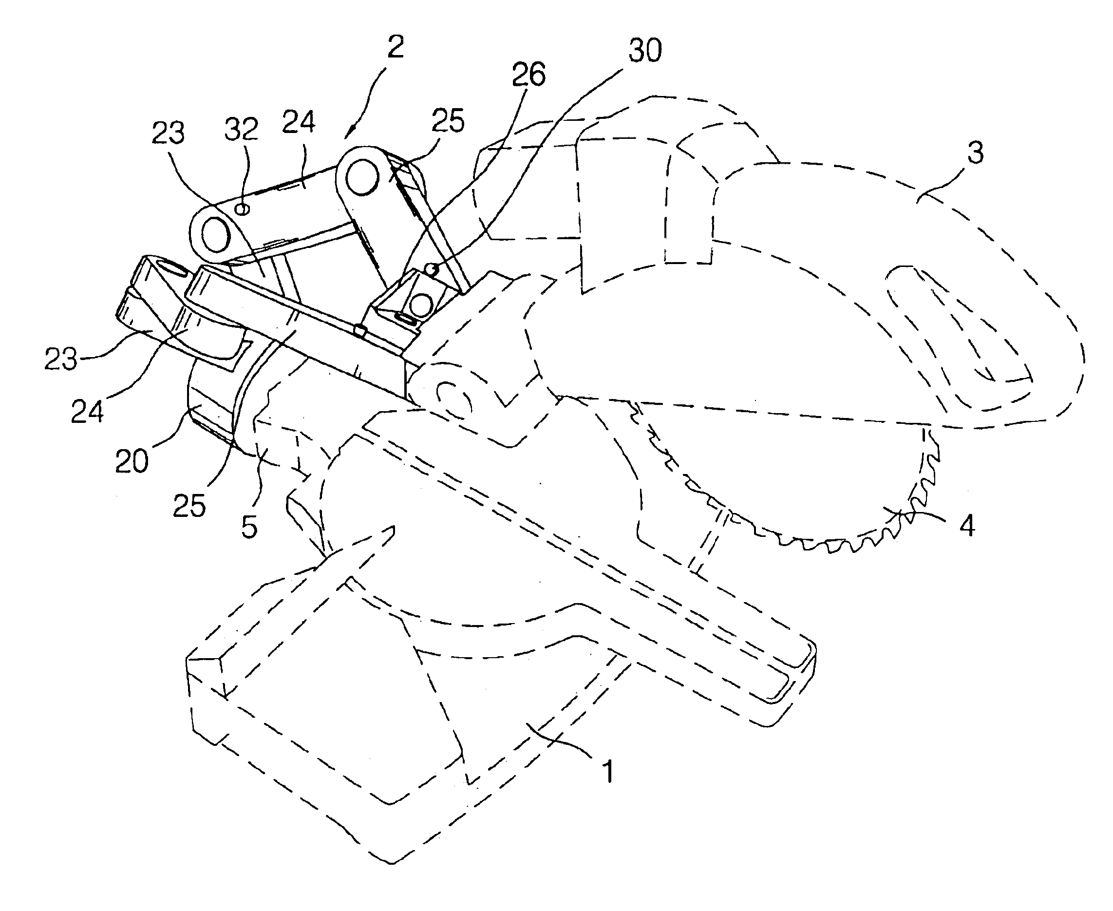
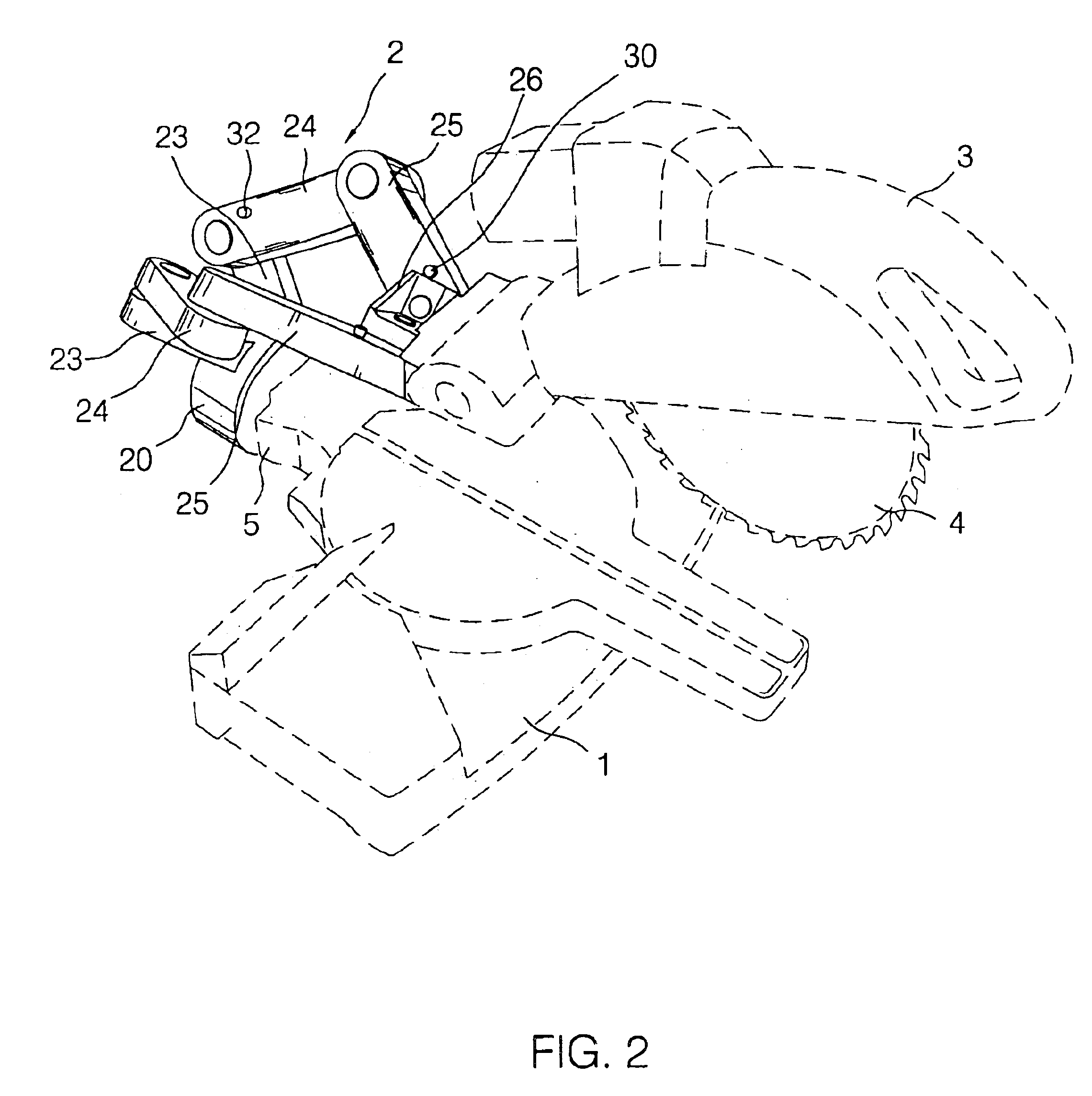
[0022]Referring to the drawings and initially to FIGS. 2-5, a circular sawing machine in accordance with the preferred embodiment of the present invention comprises a base 1, a saw seat 3 movable relative to the base 1, and a link mechanism 2 pivotally mounted between the base 1 and the saw seat 3, so that the saw seat 3 is linearly movable relative to the base 1.

[0023]The base 1 has a side provided with a support seat 5.

[0024]The saw seat 3 is provided with a circular saw blade 4.

[0025]The link mechanism 2 includes a positioning seat 20 secured on the support seat 5 of the base 1, two symmetrically opposite first links 23 each having a first end 230 mounted on the positioning seat 20, two symmetrically opposite second links 24 each having a first end 240 pivotally mounted on a second end 232 of a respective one of the two first links 23, and two symmetrically opposite third links 25 each having a first end 250 pivotally mounted on a second end 242 of a respective one of the two sec...


PUM


Abstract

A circular sawing machine includes a base, a saw seat movable relative to the base, and a link mechanism pivotally mounted between the base and the saw seat, so that the saw seat is linearly movable relative to the base. Thus, the link mechanism can absorb vibration or shock during operation of the circular saw blade so as to provide a shock-absorbing effect the circular saw blade, so that the circular saw blade can be operated smoothly and stably.

Description

BACKGROUND OF THE INVENTION[0001]1. Field of the Invention[0002]The present invention relates to a circular sawing machine, and more particularly to a circular sawing machine having a link mechanism.[0003]2. Description of the Related Art[0004]A conventional circular sawing machine in accordance with the prior art shown in FIG. 1 comprises a base 10 formed with a cutting slot 12 and having a side provided with a support seat 15, a movable shaft 16 slidably mounted on the support seat 15 of the base 10, a motor seat 14 secured on the movable shaft 16 to move therewith, and a saw seat 11 secured on the movable shaft 16 to move therewith. In addition, the saw seat 11 is provided with a circular saw blade 13 that can be extended into the cutting slot 12 of the base 10. Thus, when the movable shaft 16 is pushed or pulled to move forward and backward, the saw seat 11 is moved with the movable shaft 16, so that the circular saw blade 13 can be moved forward and backward in a linear manner ...

Claims


Application Information

Patent Timeline
Patent Type & Authority Patents(United States)
IPC IPC(8): B23D47/00B27B5/00B27B5/20
CPCB23D47/005B27B5/208Y10T16/54028Y10T83/7693Y10T83/7697Y10T83/7705Y10T83/7763
Inventor CHIN-CHIN, CHANG
Owner CHIN CHIN CHANG
Why Eureka
Try Eureka