
Latching mechanism for combustion chamber plate of a fastener driving tool

a technology of gas fastener and clutch mechanism, which is applied in the direction of nailing tools, hot gas positive displacement engine plants, combustion engines, etc., can solve the problems of reducing increasing the risk of costly repairs, and affecting the service life of the tool, so as to reduce the cost of manufacturing and repair, and the effect of rapid burn of the fuel air mixtur

Inactive Publication Date: 2005-05-17
ILLINOIS TOOL WORKS INC
View PDF22 Cites 20 Cited by
  • Summary
  • Abstract
  • Description
  • Claims
  • Application Information

AI Technical Summary

Benefits of technology

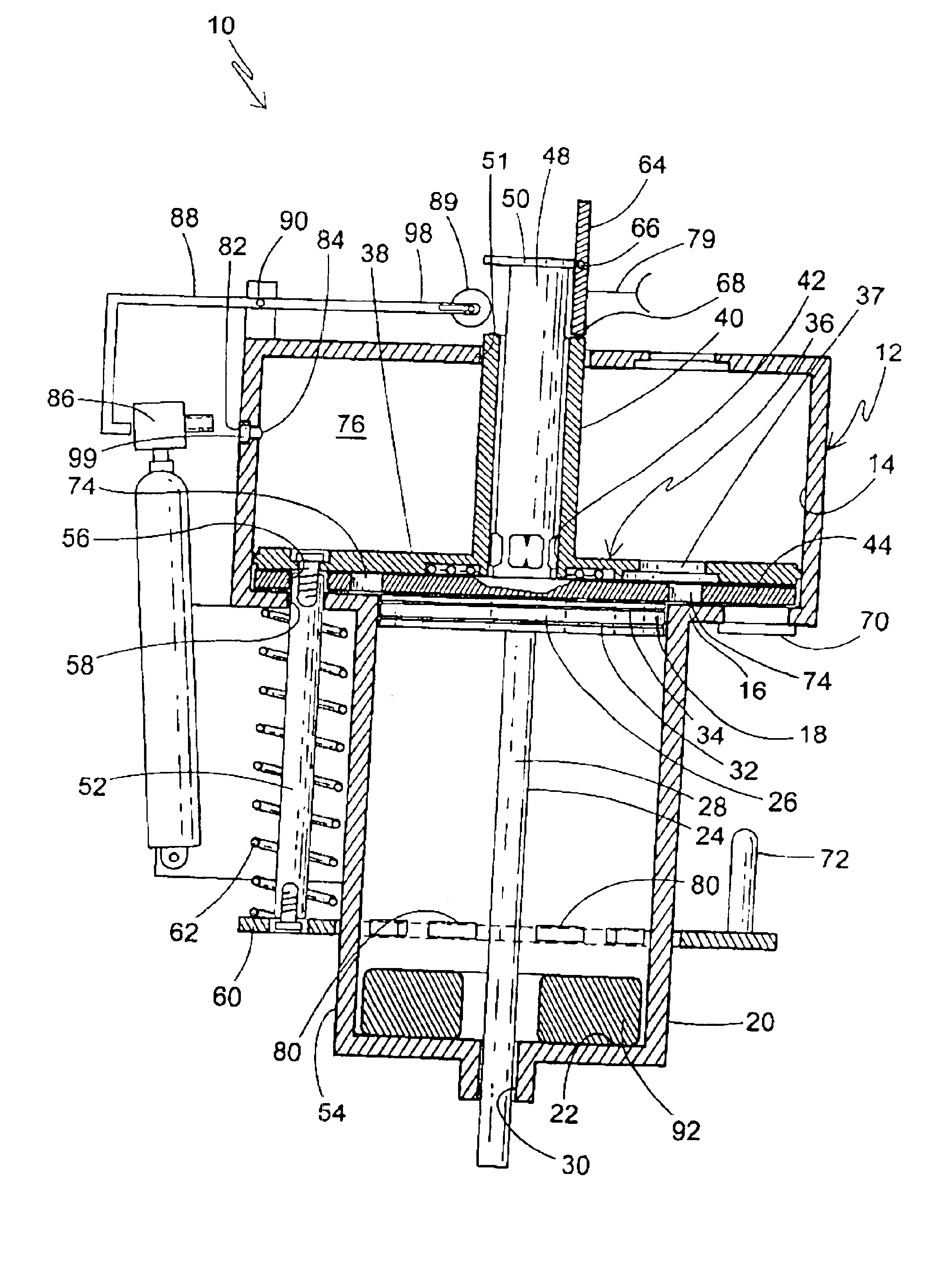
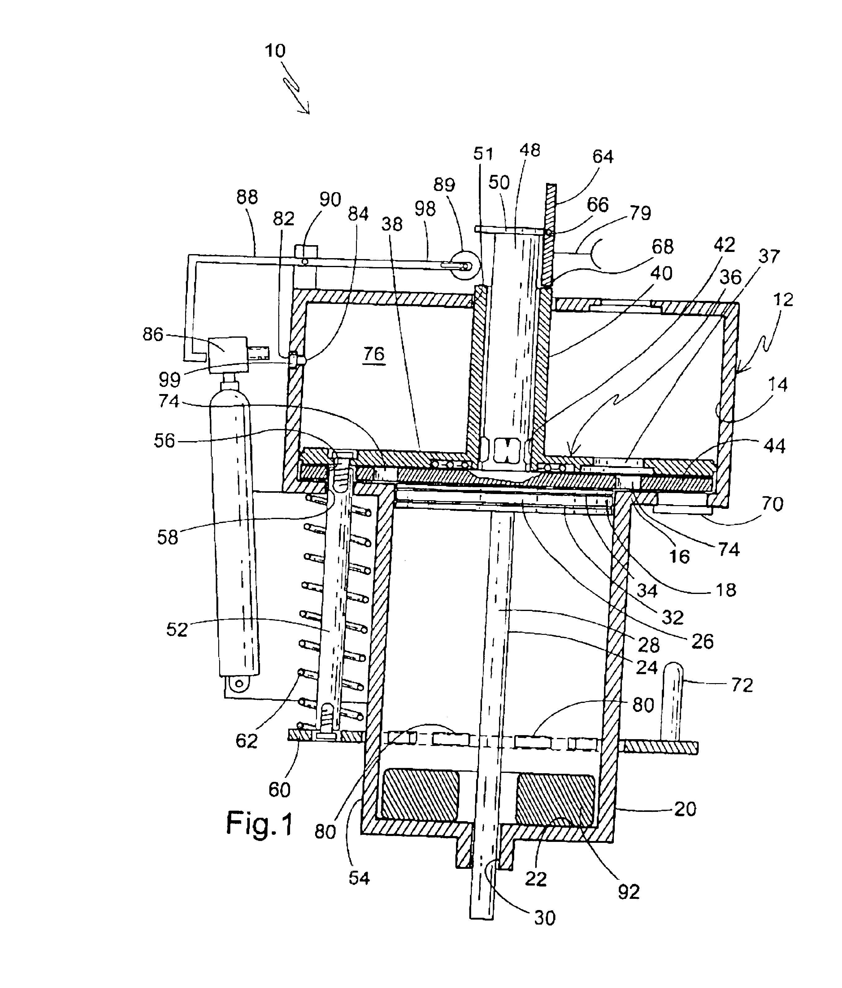
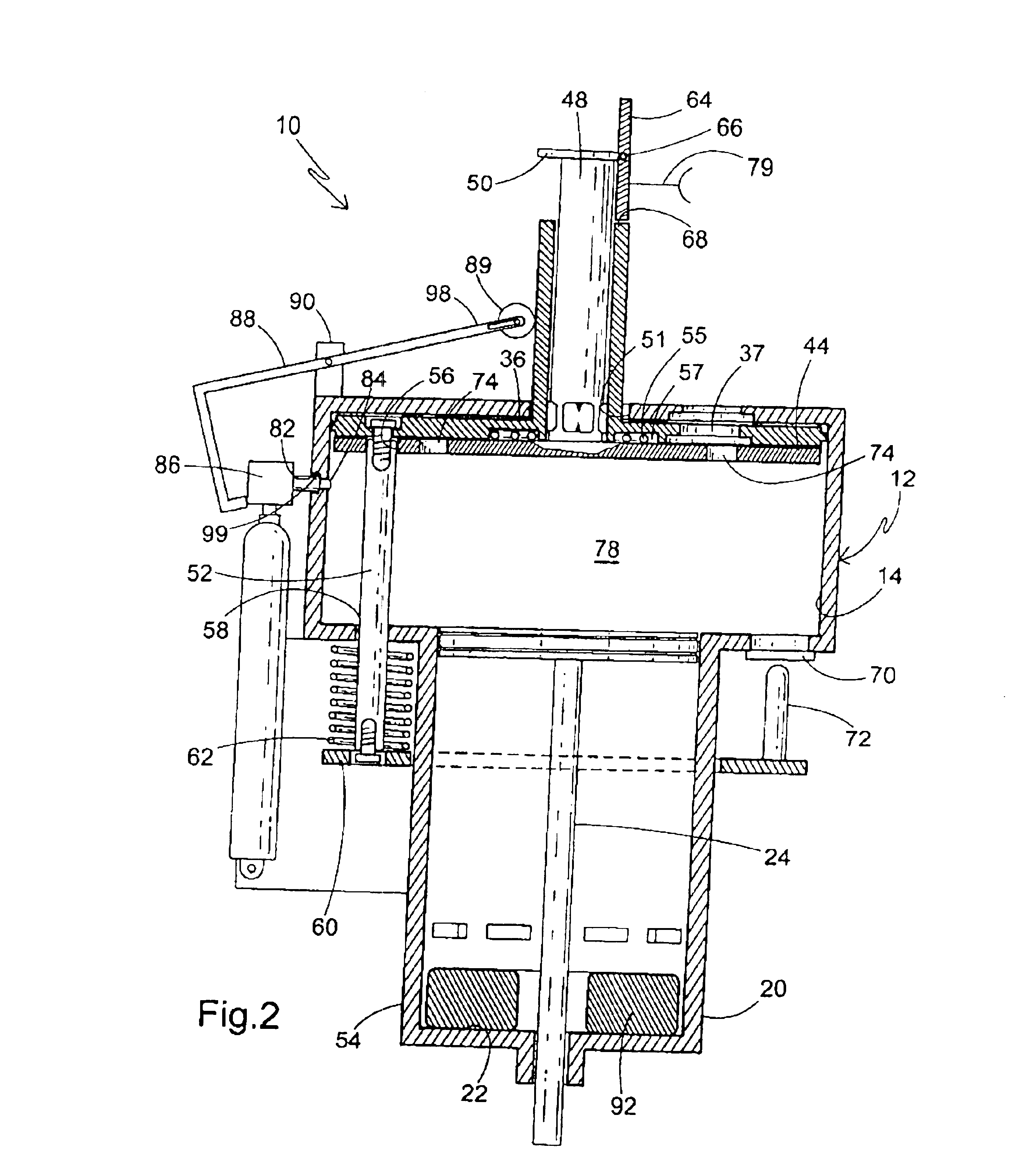
[0012]The above-listed concerns are addressed by the present combustion chamber assembly for a combustion-tool, which features a combustion chamber, at least one movable plate and a latching mechanism. The combustion chamber assembly provides a simplified movable plate that can be selectively positioned for achieving the desired fuel-air mixture. Movement of the plate is achieved by a variety of latches that are less expensive to manufacture and repair than the electric and electronic counterparts. Another feature of the present combustion chamber assembly is that the latch member also positions the movable plate in a specific location where increased pressure can be delivered to the piston early in the drive stroke. Shielding of the piston from pressure increases is also accomplished by positioning the movable plate between the regions where combustion is initiated and where the piston is housed. Still another feature of the present invention is the creation of the turbulance in the combustion chamber needed to achieve a rapid burn of the fuel air mixture.
[0013]More specifically, the present invention provides a combustion chamber assembly for use in a combustion tool including a combustion chamber having at least one combustion chamber plate disposed in the chamber and where the at least one combustion chamber plate and the chamber members are configured for relative reciprocal movement. The combustion chamber has at least one latch member associated with at least one of the combustion chamber members and the at least one combustion chamber plate for releasably holding the relative position of the at least one combustion chamber plate to the chamber during operation of the tool. A release for the latch member is also provided which permits relative movement of the at least one combustion chamber plate and the combustion chamber.

Problems solved by technology

Typically, 2.5 times the combustion chamber volume change is needed to exchange the residual combustion gas with air, making it a relatively inefficient method.
One disadvantage of the current combustion-powered tools used for fastening is that they have a multitude of components that perform the ancillary functions needed to support the basic function of the tool, such as the scavenging function.
A further disadvantage of these tools having complex components is that the additional components make the tool more susceptible to costly repairs.
This process is more difficult in the divided combustion chamber approach.
One disadvantage is that these approaches involve additional components to support the mixing process.
A further disadvantage is that these known approaches often cannot accommodate the tool when a rapid cycle is desired.

Method used


Image

  • Latching mechanism for combustion chamber plate of a fastener driving tool
  • Latching mechanism for combustion chamber plate of a fastener driving tool
  • Latching mechanism for combustion chamber plate of a fastener driving tool

Examples


embodiment 100

[0050]Referring now to FIG. 6, the embodiment 100 is depicted when the latch member 116 is released, or is moved laterally generally outward, after the trigger 79 is fully depressed, causing ignition. A second spring 132 is attached to the sleeve 108 and drives the divider plate 114 downward until a stop 134 disposed on an inner wall 135 of the sleeve 108 engages the divider plate. A first flow volume 136 and a second flow volume 138 are defined in the sleeve volume 126 by the downward displacement of the divider plate 114. The fuel-air mixture flows through holes 140 in the divider plate 114 from the second flow volume 138 to the first flow volume 136. Turbulence is thus created in the first flow volume 136 which is used to produce a faster flame speed.

[0051]Referring now to FIG. 7, combustion occurs in the first flow volume 136 by igniting the fuel air mixture when the divider plate 114 reaches the stop 134. In the preferred embodiment, ignition occurs via a spark plug as is shown...

embodiment 150

[0052]Referring now to FIGS. 8-11, another alternative combustion chamber assembly incorporating a latching mechanism is generally designated 150. Components which are shared with the latching mechanism 100 have been designated with identical reference numbers. A distinctive feature of the embodiment 150 is that the latching mechanism uses at least one spring biased latch member and a cam to engage at least one of the latch members. Another feature of the mechanism is that it increases the flow of air and fuel through openings in the divider plate 114, which maximizes the firing response time of the tool. The latching mechanisms of the combustion chamber assembly 10, 100 use a hole size in the divider plate, 44, 114 that optimizes the drive force of the piston. In some applications, the optimal hole size may be too small to allow the divider plate to snap back into the upward position after the tool has been triggered. This affects the rate at which the tool can be repeatedly fired....


PUM


Abstract

A combustion chamber assembly for use in a combustion tool including a combustion chamber, at least one combustion chamber plate disposed in the chamber, the at least one combustion chamber plate and the chamber members being configured for relative reciprocal movement, the combustion chamber assembly having at least one latch member associated with control of movement of at least one plate within the combustion chamber to divide the chamber into multiple volumes. The combustion chamber assembly further has a release for the latch member for permitting relative movement of the at least one combustion chamber plate and the combustion chamber.

Description

BACKGROUND OF THE INVENTION[0001]This invention relates to a latching mechanism for a simplified gas fastener-driving tool, in particular, a latching mechanism for use in a combustion chamber of such a tool. Such fastener-driving tools are available commercially from ITW-Paslode (a division of Illinois Tool Works, Inc.) of Vernon Hills, Ill.[0002]Combustion-powered tools, or combustion tools, are known in the art, and one type of such tools, also known as IMPULSE® brand tools for use in driving fasteners into workpieces, is described in commonly assigned patents to Nikolich U.S. Pat. Re. No. 32,452, and U.S. Pat. Nos. 4,522,162; 4,483,473; 4,483,474; 4,403,722, 5,197,646 and 5,263,439, all of which are incorporated by reference herein. Similar combustion-powered nail and staple driving tools are available commercially from ITW-Paslode of Vernon Hills, Ill. under the IMPULSE□□and PASLODE® brands.[0003]Fastener-driving tools are provided with a multitude of components necessary for pe...

Claims


Application Information

Patent Timeline
Patent Type & Authority Patents(United States)
IPC IPC(8): F01B29/00F01B29/08F02G1/00F02C5/00B25C1/08
CPCB25C1/08F02C5/00F02G1/00
Inventor VAN ERDEN, DONALD L.DOHERTY, JAMES E.ADAMS, JOSEPH S.
Owner ILLINOIS TOOL WORKS INC
Learn More