
Hard disk drive tray module

a technology for hard disk drives and modules, applied in the direction of furniture parts, instruments, electrical equipment casings/cabinets/drawers, etc., can solve the problems of not meeting the width requirements of 1u server, the width of the entire hard disk drive device, and the computer will not function properly, etc., to achieve the effect of easy installation and removal

Active Publication Date: 2005-05-10
QUANTA COMPUTER INC
View PDF5 Cites 46 Cited by
  • Summary
  • Abstract
  • Description
  • Claims
  • Application Information

AI Technical Summary

Benefits of technology

[0007]Another objective of the present invention is to provide a hard disk drive tray module with a latch that is fabricated by a powder metal injection technique. The structure of the latch can thereby be strengthened so as to prevent the latch from breaking as a result of falling.
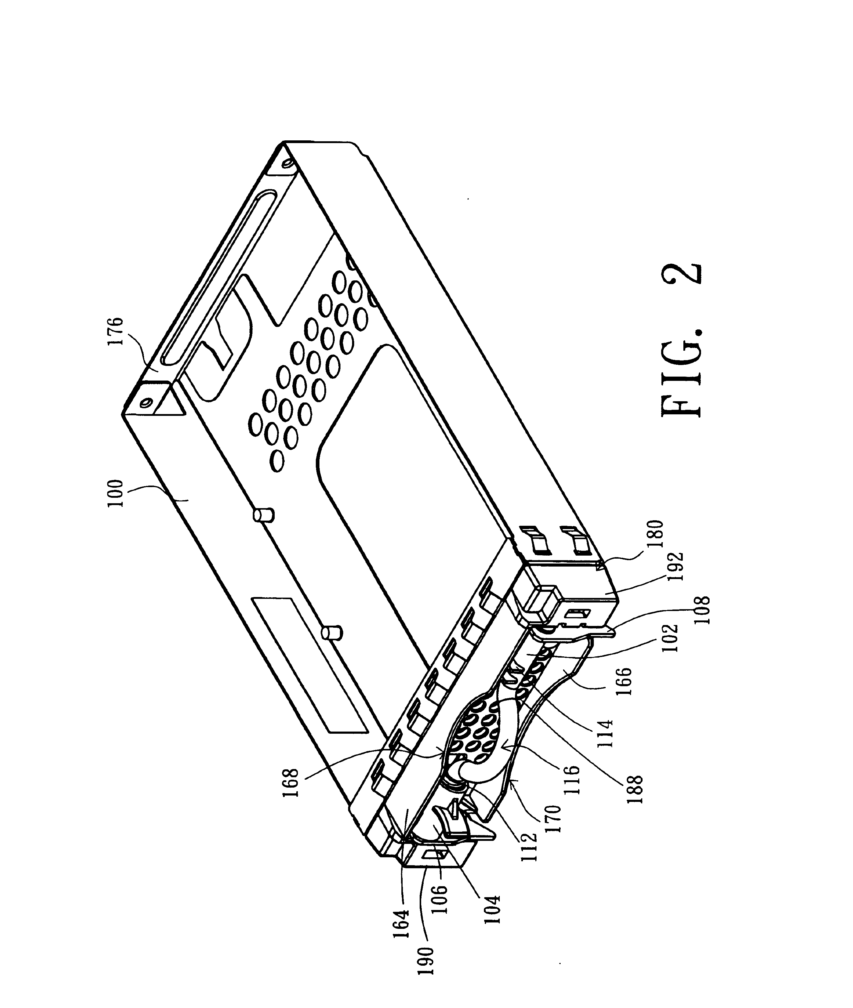
[0008]Still another objective of the present invention is to provide a hard disk drive tray module with a bezel having a concave geometry that mirrors a curved portion of a handle. The concave geometry of the bezel together with the curved portion of the handle forms a recess by which the tray can be easily installed and removed.
[0011]Because the hook device of the present invention is a latch design using the E ring and spring, the latch can be slid along the handle to release the catch. As a result, the hard disk drive tray module can be installed and removed easily. Furthermore, the latch of the hard disk drive tray module is fabricated by a powder metal injection technique such that the structure of the latch is substantially strengthened so as to withstand 32G acceleration in the falling test.

Problems solved by technology

The hard disk drive, then, is the most important data storage device on the computer because if it is damaged, the computer will not function properly, if at all.
However, the side hook design increases the width of the entire hard disk drive device such that it cannot conform to the 1U server standard width requirement.
Moreover, most current hard disk drive tray designs cannot bear an acceleration exceeding 32G and are broken easily during a falling test with 32G acceleration.

Method used


Image

  • Hard disk drive tray module
  • Hard disk drive tray module
  • Hard disk drive tray module

Examples


Embodiment Construction

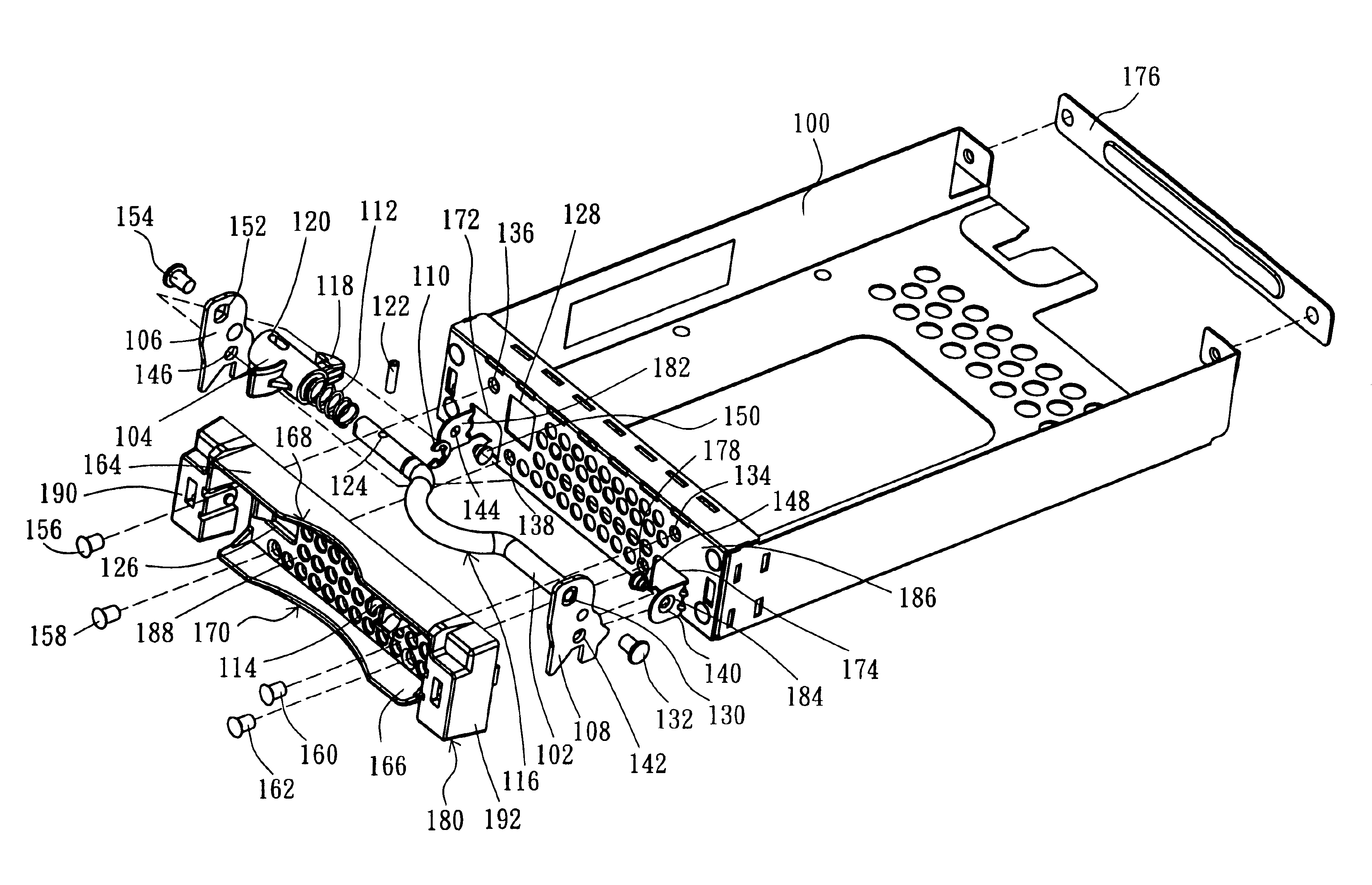
[0016]The present invention discloses a hard disk drive tray module with a hook device that is composed of a latch, an E ring, a spring and a handle. The E ring and the spring can be slid along the handle allowing the hard disk drive tray module to be installed and removed easily. Moreover, with the use of a powder metal injection technique, the structure of the latch can be strengthened to prevent the latch from being broken. In order to make the illustration of the present invention more explicit, the following is described with reference to FIGS. 1-3.

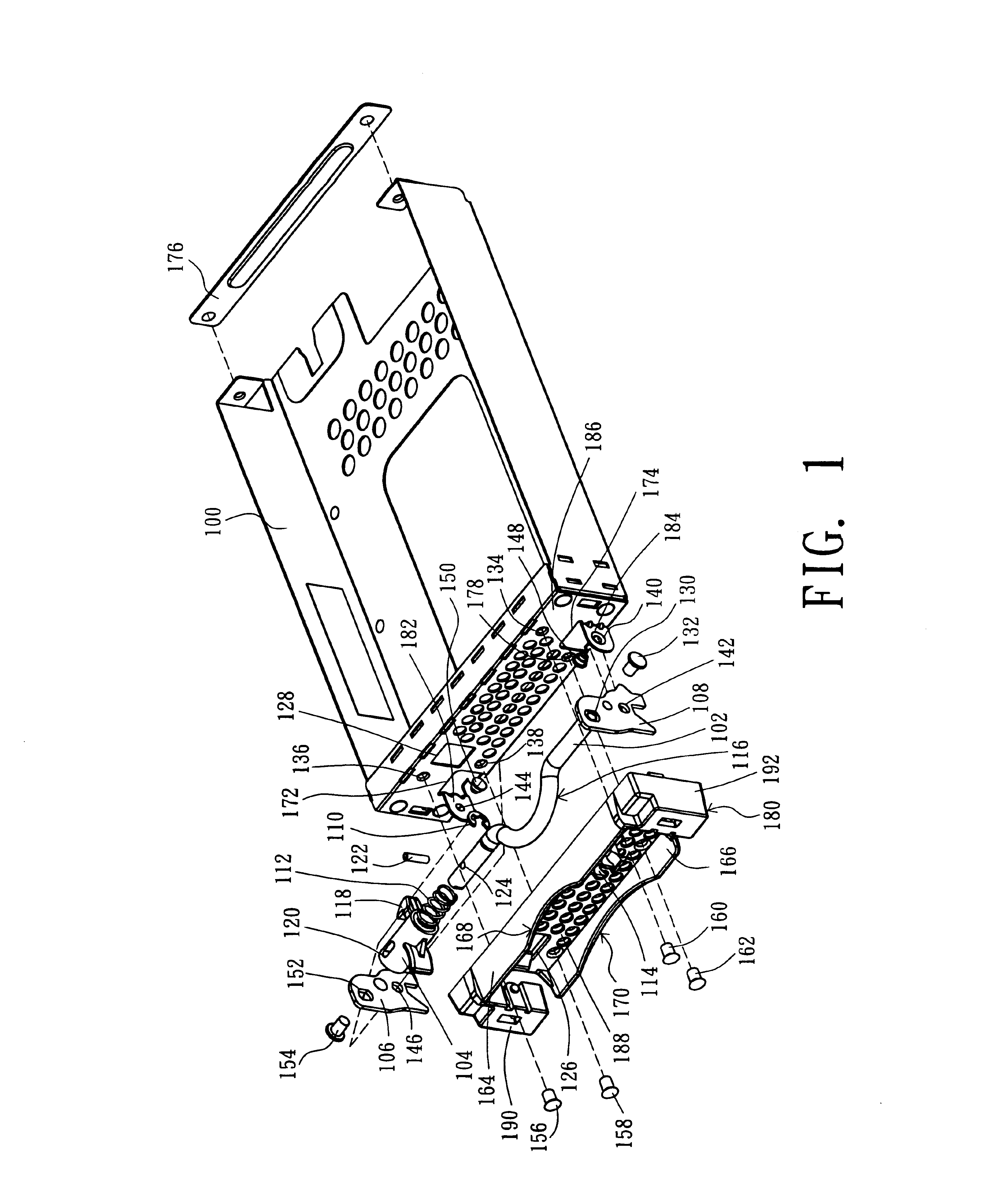
[0017]Referring to FIG. 1, a schematic diagram is shown of the assembling of a hard disk drive tray module in accordance with a preferred embodiment of the present invention. The hard disk drive tray module is mainly composed of a tray 100 into which a hard disk drive can be installed. The tray has a catch hole 128 in a front plate 186; and a hook hole 172 and a hook hole 174 are respectively located on the two sides of the lower edg...


PUM


Abstract

A hard disk drive (HDD) tray module is disclosed. The hard disk drive tray module comprises a tray, a bezel and a hook device, wherein the bezel is located between the tray and the hook device, and the hook device and the bezel are attached to the tray. The hook device comprises a handle, a latch, a spring, an E ring and two hook plates, wherein the handle is inserted into the spring, the spring is inserted into the latch, and the E ring is installed onto the handle. With the use of the spring and the E ring, the latch can be slid along the handle.

Description

RELATED APPLICATIONS[0001]The present application is based on, and claims priority from, Taiwan Application Serial Number 93201175, filed Jan. 20, 2004, the disclosure of which is hereby incorporated by reference herein in its entirety.FIELD OF THE INVENTION[0002]The present invention relates to a hard disk drive (HDD) tray module, and more particularly, to a hard disk drive tray module that is assembled rigidly and installed easily.BACKGROUND OF THE INVENTION[0003]A hard disk drive is a major data storage device of a computer. The hard disk drive is used to store data, and the overwhelming majority of the data necessary to operate the hardware and software of the computer is stored on the hard disk drive. The larger the capacity of the hard disk drive, the more data the computer can store. The hard disk drive, then, is the most important data storage device on the computer because if it is damaged, the computer will not function properly, if at all.[0004]A hard disk drive is mainly...

Claims


Application Information

Patent Timeline
IPC IPC(8): G11B33/02
CPCG11B33/025
Inventor LIN, CHENG-WANGCHEN, YU-LIN
Owner QUANTA COMPUTER INC
Learn More