
Anti-glare protection device

a protection device and anti-glare technology, applied in the direction of eye masks, goggles, garments, etc., can solve the problems of loss of functional security, and achieve the effects of reducing manufacturing costs, preventing accidental damage, and preventing accidental damag

Inactive Publication Date: 2005-05-10
SPERIAN WELDING PROTECTION +1
View PDF7 Cites 14 Cited by
  • Summary
  • Abstract
  • Description
  • Claims
  • Application Information

AI Technical Summary

Benefits of technology

[0008]The invention is directed toward creating an anti-glare protection device comprising a supporting part, a protective plate and an optical filter element arranged behind the protective plate, which anti-glare protection device provides, with a minimum additional manufacturing effort, a better protection of the filter element and, in the case of an active filter element, a better protection of the sensor belonging to the active filter element, and simultaneously provides an enhanced protection of the wearer against gases, smoke and dirt than is possible with corresponding devices in accordance with prior art.
[0009]The anti-glare protection device according to the invention comprises a seal between the supporting part and the protective plate or between the filter element and the protective plate. The seal extends around the sight opening, and prevents contamination with dirt and undesirable gases inside the anti-glare protection device to a high degree. The seal, therefore, represents a very simple, but nonetheless very effective, improvement of known anti-glare protection devices.
[0010]The seal of the anti-glare protection device in accordance with the invention consists of an elastically compressible material and is dimensioned such that the protective plate lies gastight against the supporting part or against the filter element in every condition of the anti-glare protection device. Furthermore, the seal has a shock-absorbing effect such that the protective plate is able to survive mechanical influences, such as blows, without suffering damage.

Problems solved by technology

It becomes manifest that filter elements and sensors necessary for active filter elements of anti-glare protection devices, even if they are protected towards the outside by the protective plate, get contaminated with dirt relatively quickly and consequently lose their functional security.

Method used


Image

  • Anti-glare protection device
  • Anti-glare protection device

Examples


Embodiment Construction

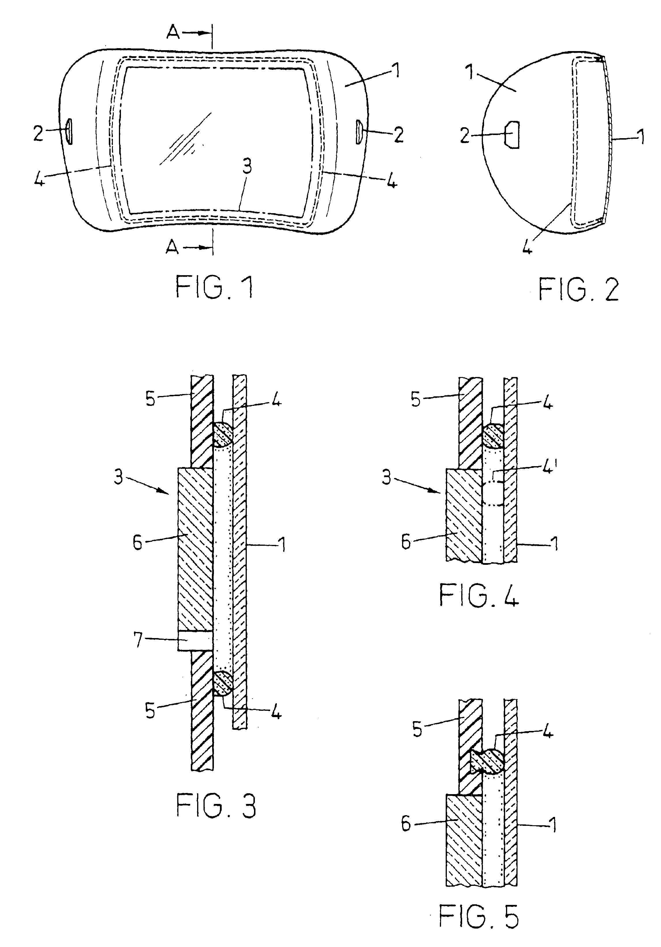
[0016]FIGS. 1 and 2 illustrate an exemplary protective plate 1 for an anti-glare protection device according to the invention. FIG. 1 is a front view of the plate, while FIG. 2 is a section as seen along line A—A of FIG. 1. The protective plate is laterally arched towards the rear and comprises lateral slits 2, with the help of which the protective plate is affixed, e.g. snapped onto a supporting part (not illustrated). FIG. 1 shows the contour of the sight opening 3 of the supporting part as a dot-dash line. A seal 4 extends around this sight opening 3, the seal being affixed to the protective plate.

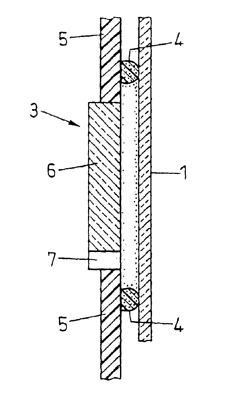
[0017]FIG. 3 illustrates as a detail a section through protective plate 1, supporting part 5 with sight opening 3 and through a filter element 6 with sensor 7 arranged in the sight opening. The seal 4 is visible between the protective plate 1 and the supporting part 5. The seal 4 is, in the illustrated case, affixed to the supporting part 5.

[0018]FIG. 4 depicts a similar section as FIG....


PUM

PropertyMeasurementUnit
transmittanceaaaaaaaaaa
light intensityaaaaaaaaaa
optical transmittanceaaaaaaaaaa

Abstract

An anti-glare protection device, for example a pair of welding goggles, a welding mask or a welding helmet, includes a supporting part with a sight opening (3), an optical filter element arranged in the sight opening, and a protective plate (1), which is mounted or can be mounted on the supporting part such covering the optical filter element. For the protection of the filter element against contamination with dirt and in order to protect the wearer of the anti-glare protection device against undesirable gases, smoke and dirt, a seal (4) made out of an elastically compressible material is disposed either between the supporting part and the protective plate (1) or between the filter element and the protective plate (1). The seal extends substantially around the sight opening and is advantageously affixed either to the supporting part, to the protective plate (1), or to the filter element.

Description

BACKGROUND OF THE INVENTION[0001]1. Field of the Invention[0002]The invention relates to an anti-glare protection device and, more particularly, toward an anti-glare protection device that is used on a pair of welding goggles, a welding mask, or a welding helmet and comprises a supporting part with a sight opening, a protective plate covering the sight opening, and an optical filter element arranged behind the protective plate.[0003]2. Description of Related Art[0004]A supporting part of welding goggles, welding masks or welding helmets, apart from its supporting function, serves to protect the welder against mechanical influences and against heat radiation. This supporting part usually consists of a plastic material, for example, of poly-carbonate and is manufactured by injection molding or by press molding.[0005]The filter element is arranged in the sight opening of the supporting part and serves as optical protection for the wearer and, therefore, represents the actual anti-glare...

Claims


Application Information

Patent Timeline
Patent Type & Authority Patents(United States)
IPC IPC(8): A61F9/02F16P1/00F16P1/06A61F9/06
CPCF16P1/06A61F9/029A61F9/06
Inventor SCHINDELE, RONALD
Owner SPERIAN WELDING PROTECTION
Learn More