
Auger/vehicle interface jig

a technology of vehicle interface and auger, which is applied in the direction of earth drilling, metal working equipment, drilling machines and methods, etc., can solve the problems of excessive manual the effort required to transport and utilize the available portable auger devices can expel a significant toll on the user, and the excessive manual effort associated with their implementation

Inactive Publication Date: 2005-05-10
SKARLUPKA IV JOSEPH HENRY +1
View PDF32 Cites 29 Cited by
  • Summary
  • Abstract
  • Description
  • Claims
  • Application Information

AI Technical Summary

Benefits of technology

[0018]An obvious advantage of this invention is the ability to easily secure an auger to a vehicle and then to drive it to any location where a hole is to be drilled and then to drill the hole without any further installation or adjustment of the present invention or auger. Due to the simplistic design of the invention another advantage of the present invention is its ease of installation onto any vehicle equipped with a standard after-market square tubular style vehicle hitch. The unit is secured and then removed from the vehicle's hitch by inserting and then removing a single hitch pin. The standard after-market square tubular style vehicle hitch used by the present invention is a common after-market accessory obtainable by the user from many vehicle related retail outlets. The advantage of this design provides for maximum strength and stability of the present invention while minimizing the weight of the unit and therefore manufacturing costs. Another advantage due to the design of the present invention is the ease of storing the unit when not in use; its slim design allows the user to store the unit in locations unavailable to prior invention designs, which are more bulky and heavy in nature. Another advantage arises because the auger is capable of being operated while attached to the vehicle. Again, because of the simplistic design of the present invention it allows one to secure, transport, and operate the auger without the need of any customized securing and stabilizing bracketry, unlike other designs that do which typically involves the use of the vehicles cargo rack. This allows the user to take full advantage of the vehicle's cargo rack. A further advantage of the invention is to facilitate the drilling of the hole and retracting the auger from the hole after it has been drilled. This may be accomplished by using assistive means including, but not limited to, a spring-, hydraulic-, gear-, or motorized type mechanisms mounted on the vehicle or carriage guide assembly of the present invention. Finally, a further advantage is that the present invention may be used on various types of augers without the need of additional adjustment to the present invention. The unique design of the automatically adjusting auger receiver assembly automatically adjusts to the varying dimensions of the operating handles of multiple pre-manufactured augers, allowing the auger unit to be supported and operated as it was designed by the manufacture, unlike previous inventions where the user must physically adjust the width of the supporting structure. These and other advantages of the present invention will become apparent upon review of the drawings, detailed description of the device, and the appended claims.
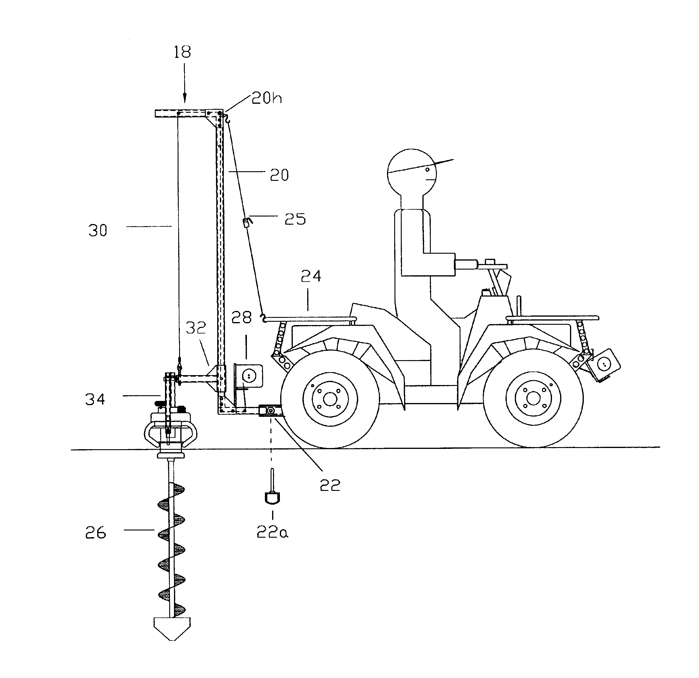
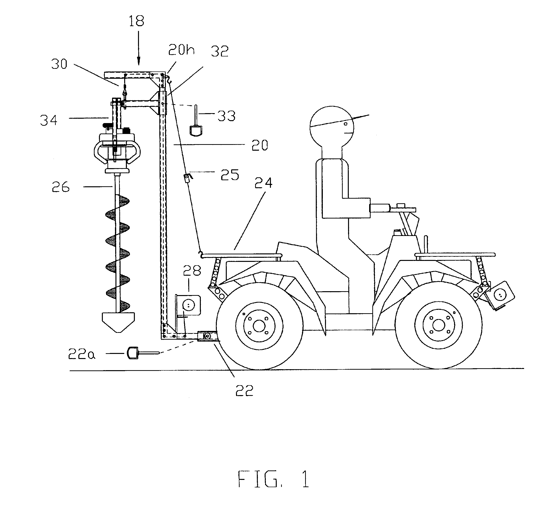
[0019]FIG. 1 is a side view of the present invention secured to an ATV while holding an auger in the fully raised position.
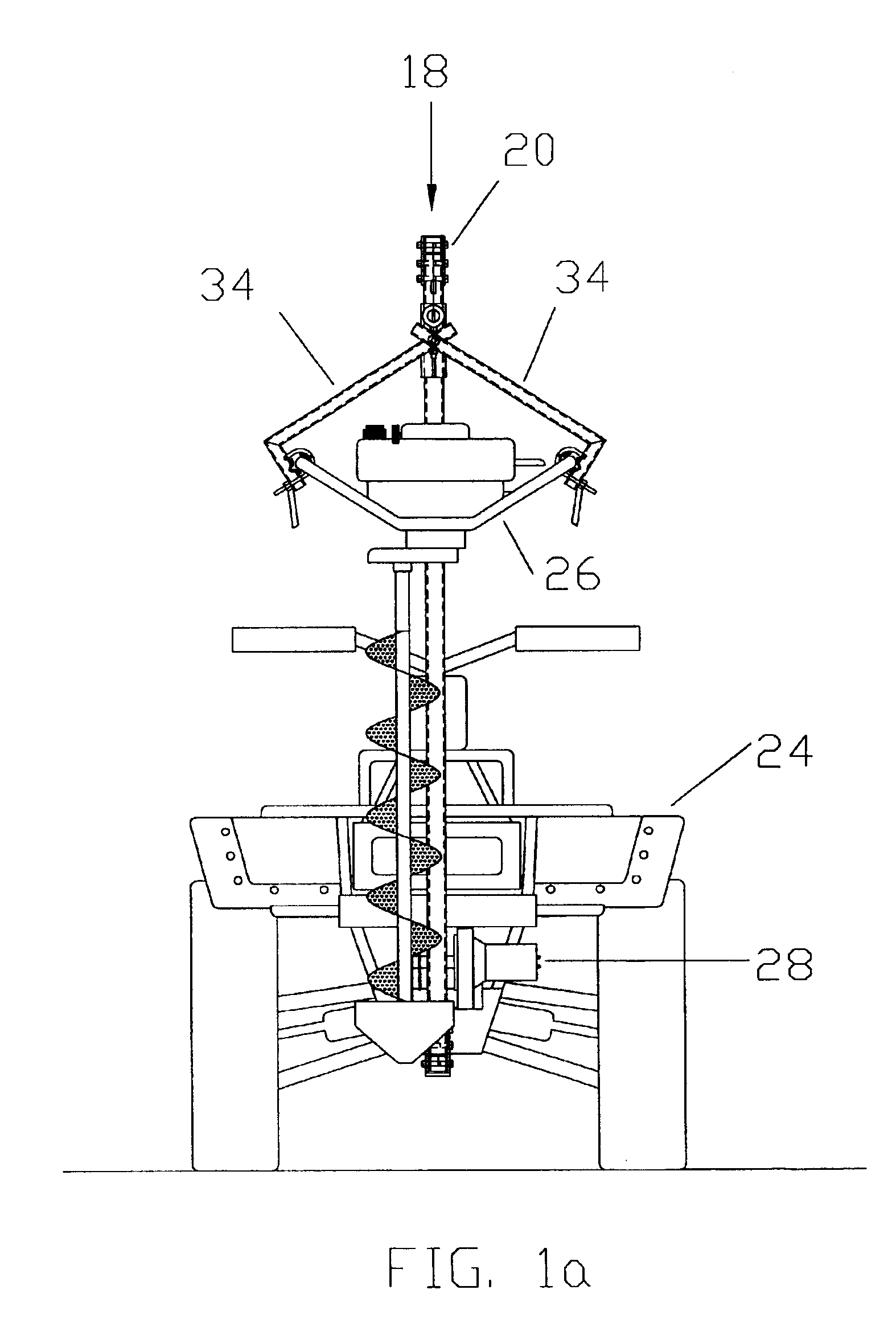
[0020]FIG. 1a is a front view of the present invention secured to an ATV while holding an ice auger in the fully raised position.
[0021]FIG. 2 is a side view of the present invention secured to an ATV while holding an auger in the fully lowered position.
[0022]FIG. 2a is a front view of the present invention secured to an ATV while holding an ice auger in the fully lowered position.
[0023]FIGS. 3 & 3a show a side and front view respectively of the present invention with an ice auger in the fully raised position.

Problems solved by technology

Whereas these devices work well for what they were designed to do, which is to drill a small diameter hole in either earth or ice, they generally require excessive manual effort to transport and utilize.
The effort required to transport and utilize the available portable auger devices can expel a significant toll on the user.
When using these devices there is generally excessive manual effort associated with their implementation.
This will cause undo stress to the human body and will lessen the production and lengthen the time required to perform the task at hand.
This also limits the use of such devices to only those people physically capable of performing such functions.
There have been several devices designed to assist the user in the transportation and utilization of auger devices but due to their design tend to be bulky, expensive to manufacture and therefore purchase and require far more labor from the user to install and operate than necessary.
The devices available today are designed to assist the user in the transportation and utilization of the auger but still fall short of the essential goal of taking the work out of drilling a small diameter hole.
Some of these devices do not address the transportation of the auger but solely assist the user with the operation of the auger, such as U.S. Pat. No. 3,602,321 (1971, Kortschaga) teaches the use of an auger powered by the clutch pulley of a snowmobile.
These devices require added assembly time and energy and can often be dangerous to use due to the open moving parts associated with the assembly and operation of the apparatus.
Such bulky clothing and gloves can get caught in the open moving parts.
It is also difficult for someone wearing such clothing to set up devices requiring the manipulation of small parts or to operate a device that requires precise movements.
Another problem associated with these devices is that they take up space in the cargo rack of the supporting vehicle and / or must be secured to the user's vehicle during transportation and then requiring additional assembly once onsite.
This requires time and the expenditure of energy, thus detracting from the safety and fulfillment of the task at hand.
The Reese device fails to address many of the problems associated with the stabilization, transportation and operation of the auger.
While the Reese device may provide more stability than a hand-held auger, the device may still twist or loosen, depending on the vibration and torque exerted when drilling through the ice.
The operation of the Reese device becomes more difficult because of the setup time required to secure the pins in the ice and the rope-pulley means for retracting the auger from the hole.
The problem with this design as it relates to securing it to a vehicle is that it not only requires custom designed bracketry to secure the Jones device to a vehicle but also requires additional brackety to stabilize the Jones device and therefore the auger it supports during the transportation process and the hole drilling operation of the auger unit.
This additional supporting bracketry not only adds additional weight which must be carried by the supporting vehicle but also adds an additional cost to the user in both monetary terms when purchasing the Jones device and in time spent in assembling the Jones device to the supporting vehicle.
The problem with this design as it relates to the ability to adapt to multiple pre-manufactured augers is that the entire apparatus of the Jones design must be physically adjusted, most likely requiring tools, to accommodate differing auger unit widths rather that just adjusting the portion of the unit that supports the powered auger device or having an auger supporting unit that automatically adjusts to the varying handling sizes and widths of multiple pre-manufactured powered auger devices.
Such bulky clothing and gloves can make it difficult to make such adjustments required by the Jones device not to mention it also adds weight, bulk, cost and time to the end-user.

Method used


Image

  • Auger/vehicle interface jig
  • Auger/vehicle interface jig
  • Auger/vehicle interface jig

Examples


Embodiment Construction

[0071]The preferred embodiment of the present invention is illustrated in FIGS. 1 through 10. FIGS. 1 through 2a show various views of a basic version of the auger / vehicle interface jig 18 in various states of use. The three main components or assemblies of the auger / vehicle interface jig 18 are illustrated in these same figures and consist of a carriage guide assembly 20, a sliding carriage assembly 32 and an automatically adjusting auger receiver assembly 34. The sliding carriage assembly 32 is affixed to the carriage guide assembly 20 by such means that it is able to move vertically up and down along the vertical support 20d of the carriage guide assembly 20. The automatically adjusting auger receiver assembly 34 is then connected to the opposite end of the sliding carriage assembly 32. The auger / vehicle interface jig 18 is made of tubular steel, however, it is to be understood that all or portions of the auger / vehicle interface jig 18 may be made from materials such as other for...


PUM


Abstract

An interface jig for removably securing a portable auger to a vehicle includes a carriage guide assembly, a sliding carriage assembly and a receiver assembly. The carriage guide assembly includes a vertical support having an upper portion and a bottom portion. A hitch adapter is affixed to the bottom portion to secure the carriage guide assembly to a vehicle hitch receiver. The sliding carriage assembly includes a horizontal member having a first end opposite a second end. The first end Is affixed to a vertical member that slides along the vertical support between the upper portion and the lower portion of the carriage guide. The receiver assembly is attached to the second end of the sliding carriage assembly.

Description

CROSS-REFERENCE TO RELATED APPLICATIONS[0001]CROSS-REFERENCE TO RELATED APPLICATIONS2723835November 1955Reese3602321August 1971Kortschaga175 / 183731751May 1973Rusco5363925November 1994Gallagher173 / 1865836402November 1998Jones173 / 1856076617June 2000Berner175 / 185330014July 1994Wagner175 / 186155771December 2000Montz414 / 543STATEMENT REGARDING FEDERALLY SPONSORED RESEARCH OR DEVELOPMENT[0002]Not ApplicableREFERENCE TO SEQUENCE LISTING, A TABLE, OR A COMPUTER PROGRAM LISTING COMPACT DISK APPENDIX[0003]Not ApplicableBACKGROUND OF THE INVENTION[0004]1. Field of Invention[0005]The present invention relates to devices for attaching auger type devices to vehicles for the purpose of easy and safe transportation of the auger and then to provide support and control of the auger during operation whether this operation is initiated remotely, from the vehicle, or locally in reference to the auger.[0006]2. Description of the Prior Art[0007]Throughout history man has found a need to excavate small diame...

Claims


Application Information

Patent Timeline
Patent Type & Authority Patents(United States)
IPC IPC(8): E21B7/02
CPCE21B7/028
Inventor SKARLUPKA, IV, JOSEPH HENRYSKARLUPKA, KARA JEAN
Owner SKARLUPKA IV JOSEPH HENRY
Learn More