
Recoil mitigation device

a technology of mitigation device and coil, which is applied in the direction of liquid ejecting gun, white arms/cold weapons, weapons, etc., can solve the problems of complex and expensive hydraulics, pistons, springs, and other problems, to achieve the effect of reducing the risk of re-entry, avoiding re-entry, and avoiding re-entry

Inactive Publication Date: 2005-05-10
BATTELLE MEMORIAL INST
View PDF22 Cites 26 Cited by
  • Summary
  • Abstract
  • Description
  • Claims
  • Application Information

AI Technical Summary

Benefits of technology

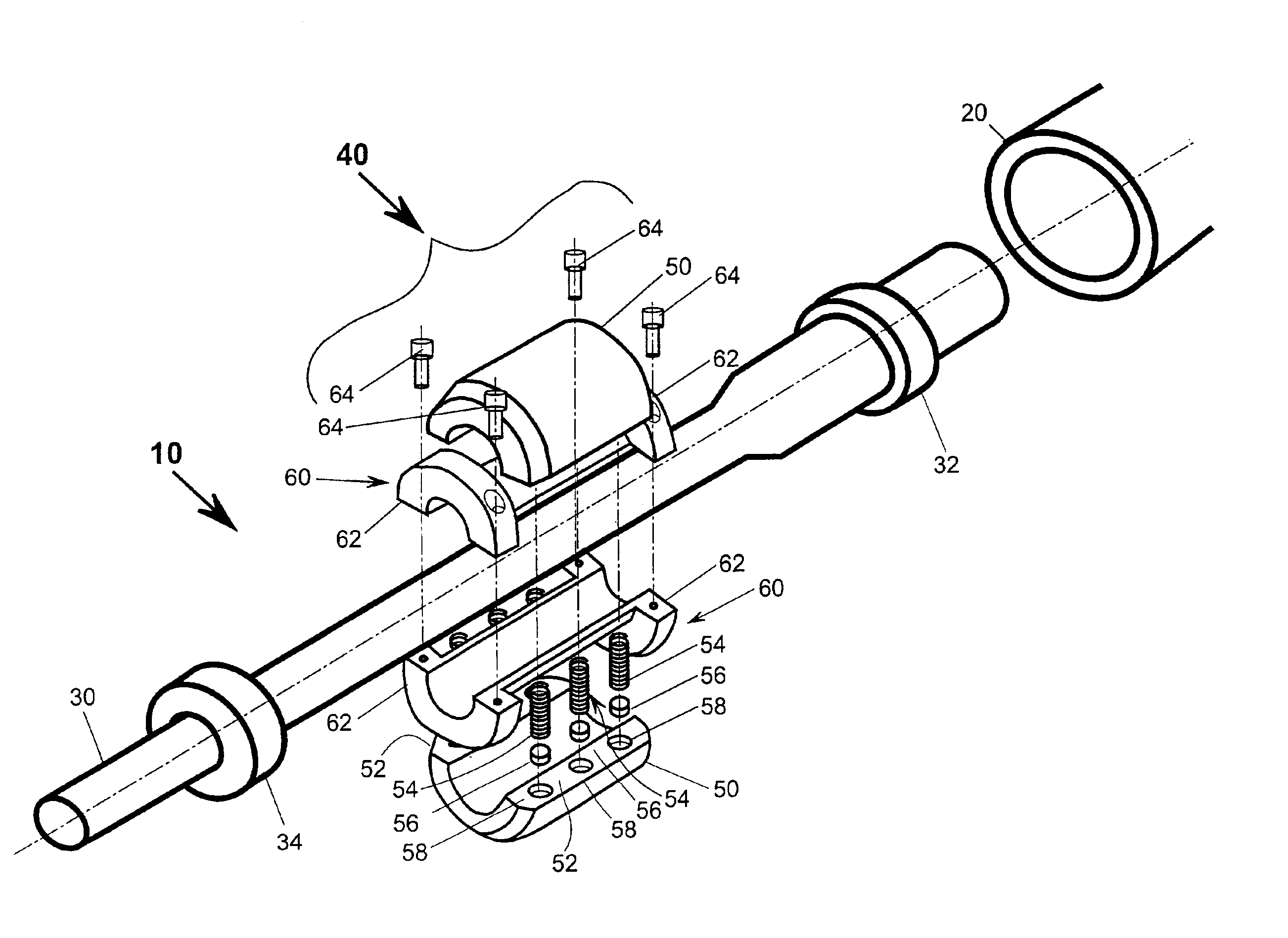
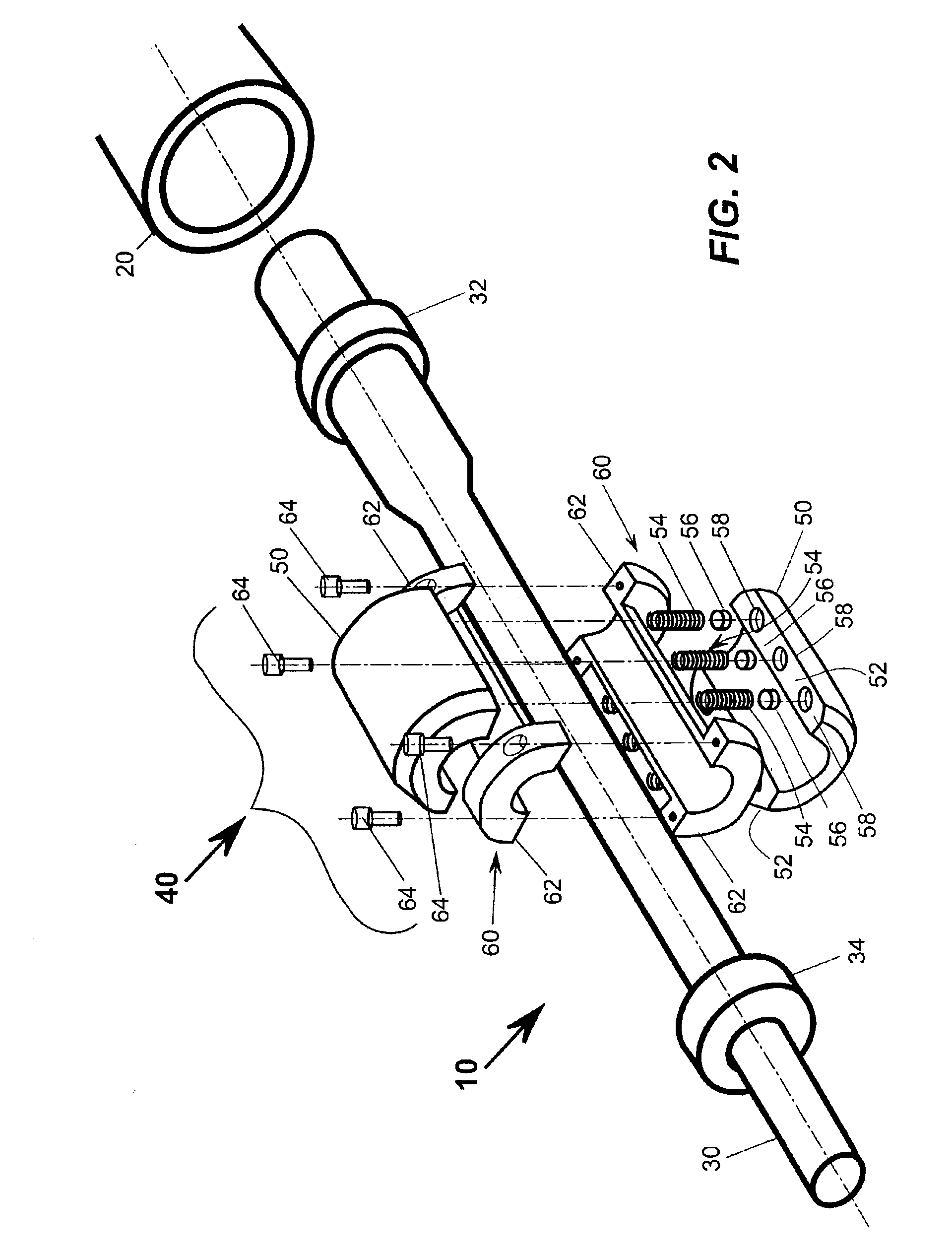
[0010]In a preferred embodiment of the present invention, the barrel of a projectile-firing device is adapted to include a pair of flanges around the outer surface of the barrel. The flanges are in a facing, spaced-apart relationship such that a pair of substantially semi-cylindrical brake shoes is accommodated therebetween in a nesting position preventing lateral movement of the brake shoes relative to the barrel while allowing the brake shoes to move radially relative to the barrel. Coil or other suitable springs are provided between the edges of each brake shoe wherein the brake shoes are urged in an outward radial direction. When the projectile-firing device, brake shoe pair, and coil spring combination is positioned coaxially within an elongated tube and a projectile fired, the springs urge the brake shoes against the inner surface of the tube creating friction and thus the recoil is mitigated. A variety of springs and / or spacers to foreshorten the springs provides the flexibility needed to match the friction to a variety of recoil mitigation needs.

Problems solved by technology

Present recoil-mitigation devices utilize complex and expensive hydraulics, pneumatics, pistons, springs, friction, or some combination thereof.
In addition, present devices are integral to the projectile-firing device and, therefore, not always easily or quickly adaptable to varying situations.
Such devices are generally of a single-shot design and produce a significant impulse—oftentimes sufficient to propel the support frame / robot backwards, cause it to topple over, and / or sustain significant damage.
Thus, the momentum generated by an explosives disrupter can be relatively significant.

Method used


Image

  • Recoil mitigation device
  • Recoil mitigation device
  • Recoil mitigation device

Examples


Embodiment Construction

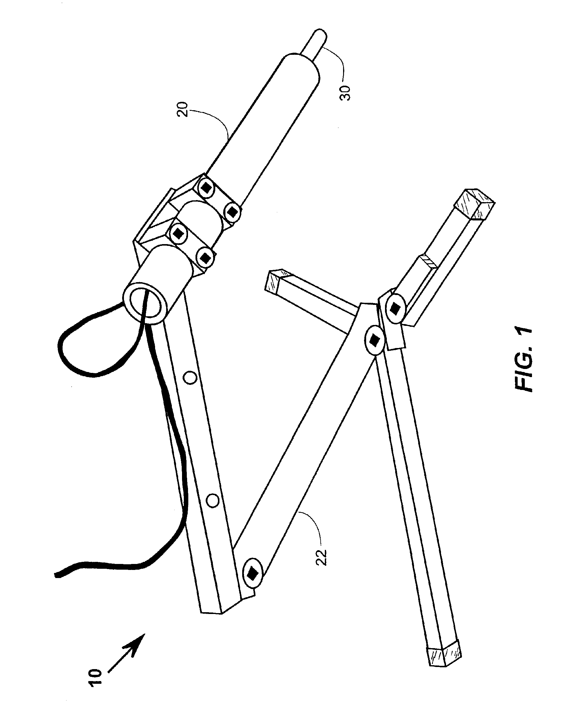
[0023]An exploded assembly view of a recoil-mitigated projectile-firing device 10 is shown in FIG. 2. Barrel 30 represents a commercially available projectile-firing device. More specifically, an explosives disrupter such as a PAN (percussion Actuated Non-electric) disrupter, distributed by Ideal Products, Lexington, Ky. under the trademark PAN DISRUPTER under license from Sandia National Laboratories, Albuquerque, N. Mex., a Lockheed Martin company, may be used. Other manufacturers of similar devices include, Royal Arms International, Woodland Hills, Calif. Such devices also typically include a breech enclosing a firing mechanism and means for firing the device (all not shown). A brake 40 is attached to the barrel 30 and the combination of the barrel 30 and the brake 40 is frictionally positioned within a guide tube 20 prior to firing. Typically, the guide tube 20 is attached to a support frame 22 (FIG. 1) or robotic device (not shown). As a reaction to the projectile being fired, ...


PUM


Abstract

A recoil mitigation apparatus for a projectile-firing device, such as an explosives disrupter, is provided. At least one brake shoe is positioned proximate the projectile-firing device and means are provided for urging the at least one brake shoe toward the projectile-firing device. The urging of the at least one brake shoe provides a frictional force to mitigate the recoil of the projectile-firing device. In a preferred embodiment, at least one pair of brake shoes are provided. In a further preferred embodiment, the each of the at least one pair of brake shoes are positioned in a facing, spaced apart relationship and the at least one pair of brake shoe combination is positioned in a coaxial relationship to the projectile-firing device.

Description

[0001]This application is a continuation of, and claims priority to, U.S. application Ser. No. 09 / 942,409, filed Aug. 29, 2001, entitled “Recoil Mitigation Device”, now U.S. Pat. No. 6,578,464, the disclosure of which is incorporated as if fully rewritten herein.[0002]This invention was not made by an agency of the United States Government nor under contract with an agency of the United States Government.FIELD OF THE INVENTION[0003]This invention relates to projectile-firing devices and particularly to methods of mitigating the recoil of such devices. More particularly, the present invention relates to utilizing friction for mitigating the recoil of a projectile-firing device designed to de-arm an explosives device, commonly known in the art as explosives disrupters.BACKGROUND OF THE INVENTION[0004]In any gun system, or more generally, projectile-firing device, conservation of momentum provides that the momentum carried by the projectile and the gases is equal to, but in the opposit...

Claims


Application Information

Patent Timeline
Patent Type & Authority Patents(United States)
IPC IPC(8): F41A25/06F41A25/00
CPCF41A25/06F41B9/0046
Inventor EBERSOLE, JR., HARVEY NELSONDEROOS, BRADLEY G.
Owner BATTELLE MEMORIAL INST
Learn More