
Shoulder joint prosthesis

a shoulder joint and prosthesis technology, applied in the field of shoulder joint prosthesis, to achieve the effect of less sliding

Inactive Publication Date: 2005-05-03
ZIMMER GMBH
View PDF26 Cites 95 Cited by
  • Summary
  • Abstract
  • Description
  • Claims
  • Application Information

AI Technical Summary

Benefits of technology

[0005]Such an arrangement has the advantage that components of normal forces are already present relative to the longitudinal axis of the connection in both directions of rotation due to the strain in the state of rest and, with a torsional stress, can act in opposition in accordance with the distance of their line of action from the axis of rotation. A further advantage consists in the fact that contact points can be deliberately chosen through the deviation from the circular cross-section of the cone connection which do not undergo any dilation at the outer conical sleeve dependent only on the ring tension and the elasticity of the material, but rather produce an additional bending load at the sleeve, which corresponds to a softer spring effect of the sleeve and thus produces a greater pushing on path and more reliability for an achieved holding force.
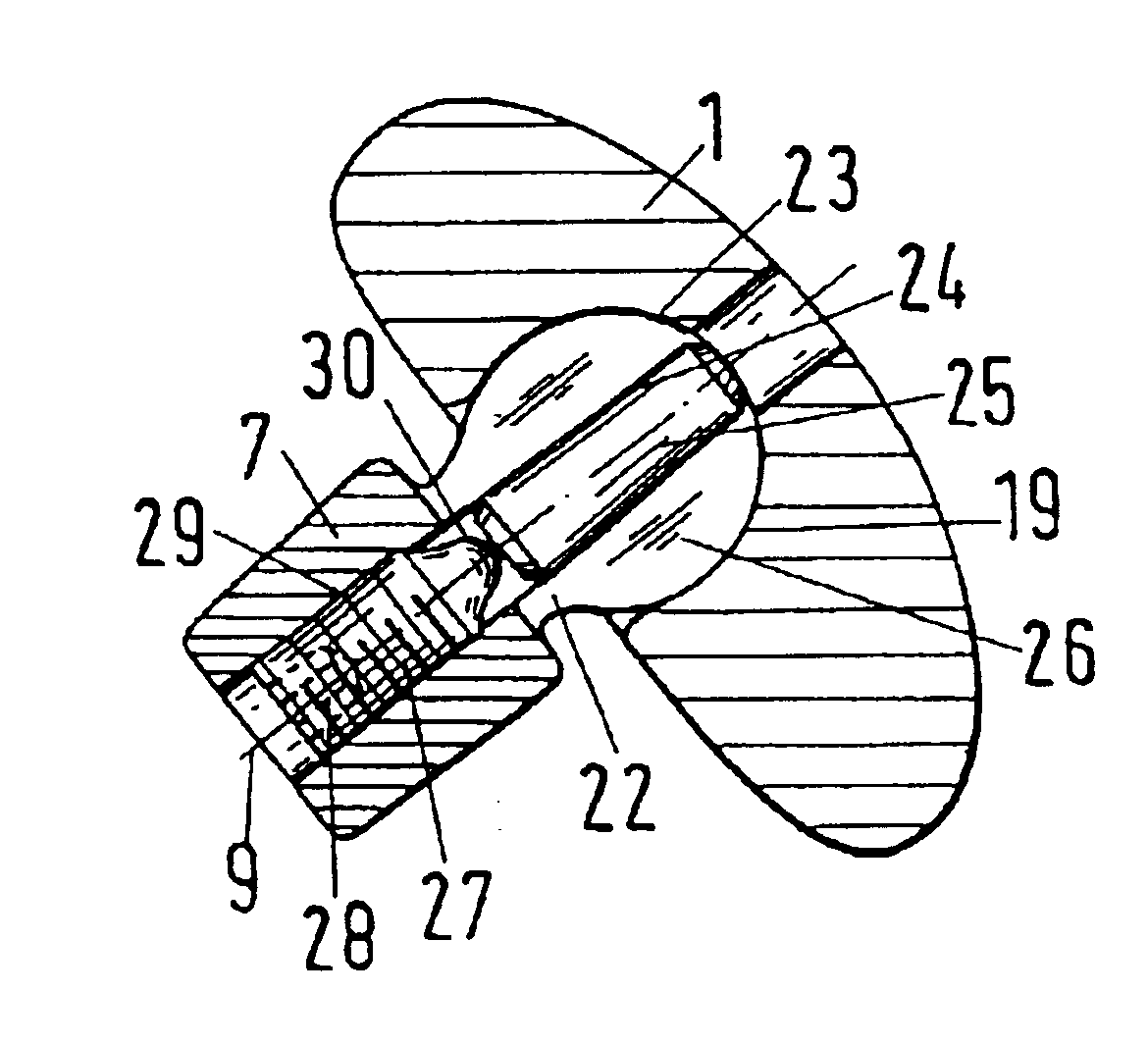
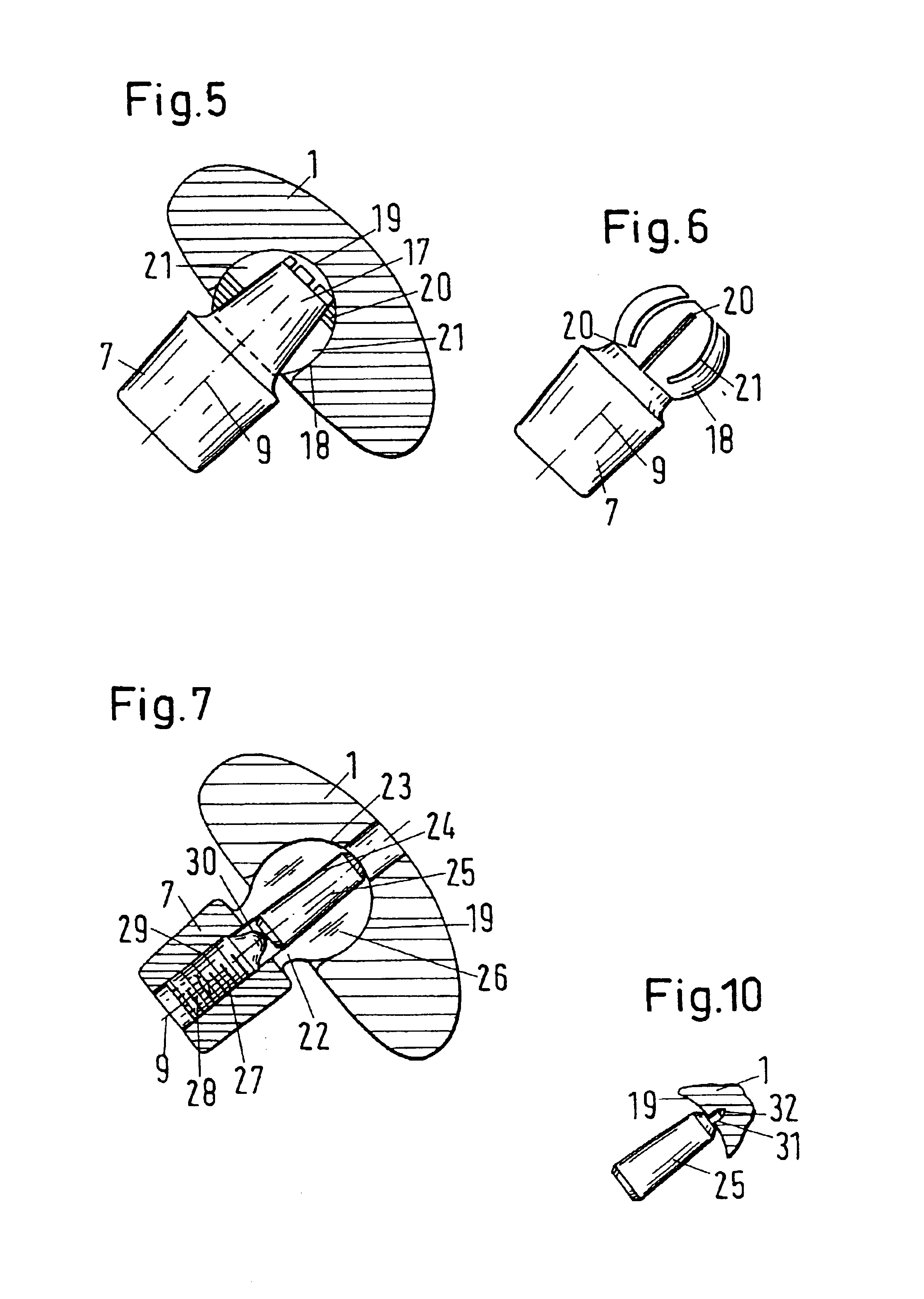
[0007]The strength of the conical connection, which is repeatedly detachable, also allows a conical body with a spherical cup to be attached to an already implanted shaft in a modification with respect to the natural shoulder joint, the spherical cup being pivotally mounted on a spherical head attached to the platform. This reversal of the joint, which allows less sliding and mainly a pivoting about the centre of the ball, is necessary when the ligaments are seriously damaged. The strength of the conical connection also allows more complex applications to be included such as are shown in the patent application FR 2727857 A1. In this publication, embodiments are shown with a shaft which ends as a longitudinally slit ball with a conical bore in order to fix the ball in a spherical recess of the bearing head via a conical pressure body. Since this ball is moulded onto the conical body of the present invention and this also receives an adjusting screw and the conical pressure body, the shaft can be initially implanted, then the best angular position of the bearing head can be fixed with a manipulating prosthesis placed on as a conical body and the same angular position can be set at a bearing head of the same size independent of the already implanted shaft. Such an angular position can additionally be secured by a pin projecting from the conical body and engaging in a matching bore in the spherical mount of the bearing head.

Problems solved by technology

Such a frictional connection is more at risk as a connection by the additionally occurring shear stresses through torsional loading, with a spread of the transmittable forces already arising from the blow by which a press-fit has to be produced and from the condition at the cone surfaces.

Method used


Image

  • Shoulder joint prosthesis
  • Shoulder joint prosthesis
  • Shoulder joint prosthesis

Examples


Embodiment Construction

[0025]In the following embodiments, the same reference symbols are used for the same functions.

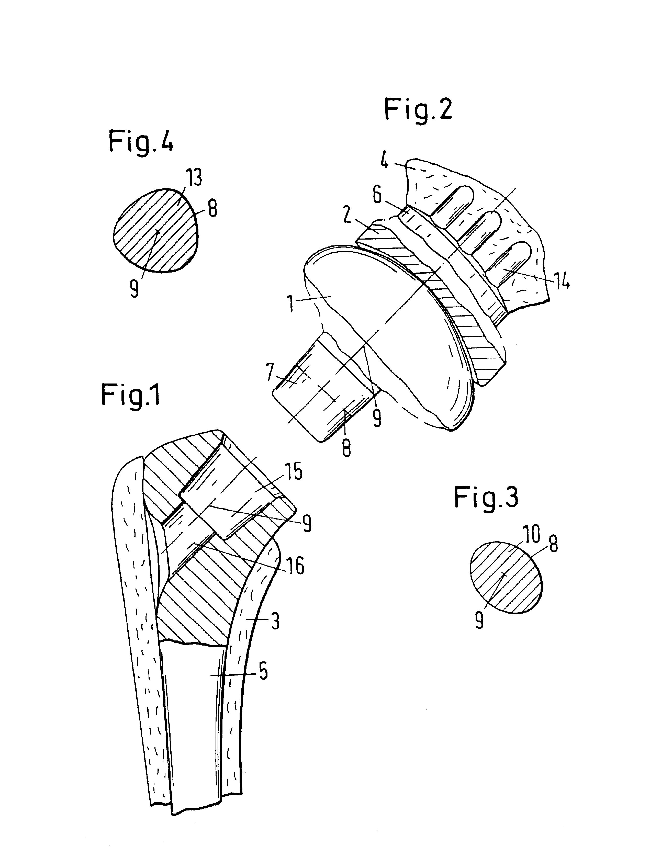
[0026]A first embodiment is shown in FIGS. 1 and 2. A shaft 5 is implanted in a humerus 3, with the shaft 5 being anchored directly in a prepared bone bed. The shaft can, however, equally well be a shaft anchored in the humerus with bone cement. A bore 16 is provided in the direction of a longitudinal axis 9 for the actual shoulder joint and ends in a mating shape 15 for a conical body 7. The actual joint is formed by a bearing head 1 rigidly connected to the conical body 7 and by a bearing shell 2 which is in turn rigidly connected to a platform 6 anchored in the shoulder bone 4. Spigots 14 are provided parallel to one another at the platform 6 to anchor the platform 6 and are anchored in prepared bores of the shoulder bone 4, for example, with bone cement or by a press fit.

[0027]The conical body 7 and, accordingly, the mating shape 15 have a cross-section 10 with a periphery 8 which, in ...


PUM


Abstract

A shoulder joint prosthesis is shown having two bearing bodies (1, 2; 11, 12) which slide on one another and which can be respectively connected to the upper arm (3) by a shaft (5) and to the shoulder bone (4) by a platform (6). When the connection to the shaft (5) is brought about by a non-rotationally symmetrical, conical body (7) with a self-locking seat, with its periphery (8) being form matched to a mating shape (15) in the shaft (5) which is rotationally fixed relative to a longitudinal axis (9) arid keyed by the taper so that the connection is releasable and repeatedly fixable in the same angular position, large forces can be transmitted by the connection.

Description

CROSS-REFERENCE TO RELATED APPLICATIONS[0001]This application claims priority of European Patent Application Nos. 01 811 120.3, filed on Nov. 21, 2001 and 02 018 730.8, filed on Aug. 21, 2002.FIELD OF THE INVENTION[0002]The invention relates to a shoulder joint prosthesis having two bearing bodies which slide on one another and which can be respectively connected to the upper arm by a shaft and to the shoulder bone by a platform.BACKGROUND OF THE INVENTION[0003]A prosthesis of this kind is shown in the patent application WO 97 / 25943. A bearing body connectable to a shaft in the upper arm has, at its lower side, a projecting cone with a circular cross-section and index bores for a pin projecting out of the shaft to fix the bearing body with its circular cone in different angular positions. With this arrangement, the index bores and the projecting pin must have a minimum clearance relative to one another so that the cone and the counter surface reliably form a connection. Due to this ...

Claims


Application Information

Patent Timeline
IPC IPC(8): A61F2/30A61F2/40A61F2/46A61F2/00A61F2/02
CPCA61F2/40A61F2/4684A61F2/4014A61F2250/0006A61F2/4059A61F2/4081A61F2/4637A61F2002/30112A61F2002/30125A61F2002/30156A61F2002/30329A61F2002/30334A61F2002/30341A61F2002/30359A61F2002/30367A61F2002/30378A61F2002/3038A61F2002/30484A61F2002/30492A61F2002/305A61F2002/30507A61F2002/30538A61F2002/30574A61F2002/30598A61F2002/30604A61F2002/30774A61F2002/3079A61F2002/30892A61F2002/4018A61F2002/4022A61F2002/4029A61F2002/4037A61F2002/4044A61F2002/4062A61F2002/4085A61F2002/4631A61F2002/4681A61F2220/0025A61F2220/0033A61F2230/0004A61F2230/0008A61F2230/0023A61F2002/30331A61F2002/30339A61F2002/30594
Inventor RAUSCHER, MARKUSWENDT, PETER
Owner ZIMMER GMBH
Learn More