
Coaxial helicopter

a coaxial helicopter and flight control technology, applied in the direction of helicopters, vehicles, rotorcraft, etc., can solve the problems of unbalance torque, increased pitch, and limited development of this type of aircra

Inactive Publication Date: 2005-05-03
AEROTWIN MOTORS
View PDF45 Cites 86 Cited by
  • Summary
  • Abstract
  • Description
  • Claims
  • Application Information

AI Technical Summary

Benefits of technology

[0008]In a further detailed aspect, the mentioned collective blade pitch control can be provided for the first and second rotors in addition to a cyclic pitch control for one of them. In further detail, a differential collective control can be provided with a collective pitch control to both rotors in addition to cyclic pitch control to one rotor, to provide a yaw control. This yaw control by collective pitch input is accomplished by providing a counterbalancing difference in pitch, and thereby a differential rotational resistance between the upper and lower rotors of the coaxial rotor set, which induces yaw of the aircraft without changing the rotor set thrust vector.

Problems solved by technology

However, because of difficulties involved in the control of cyclic and collective pitch of rotor blades in a coaxial configuration, development of this type of aircraft has heretofore been limited.
Pitch is increased in one rotor, and decreased in the other, to unbalance torque.

Method used


Image

  • Coaxial helicopter
  • Coaxial helicopter
  • Coaxial helicopter

Examples


Embodiment Construction

)

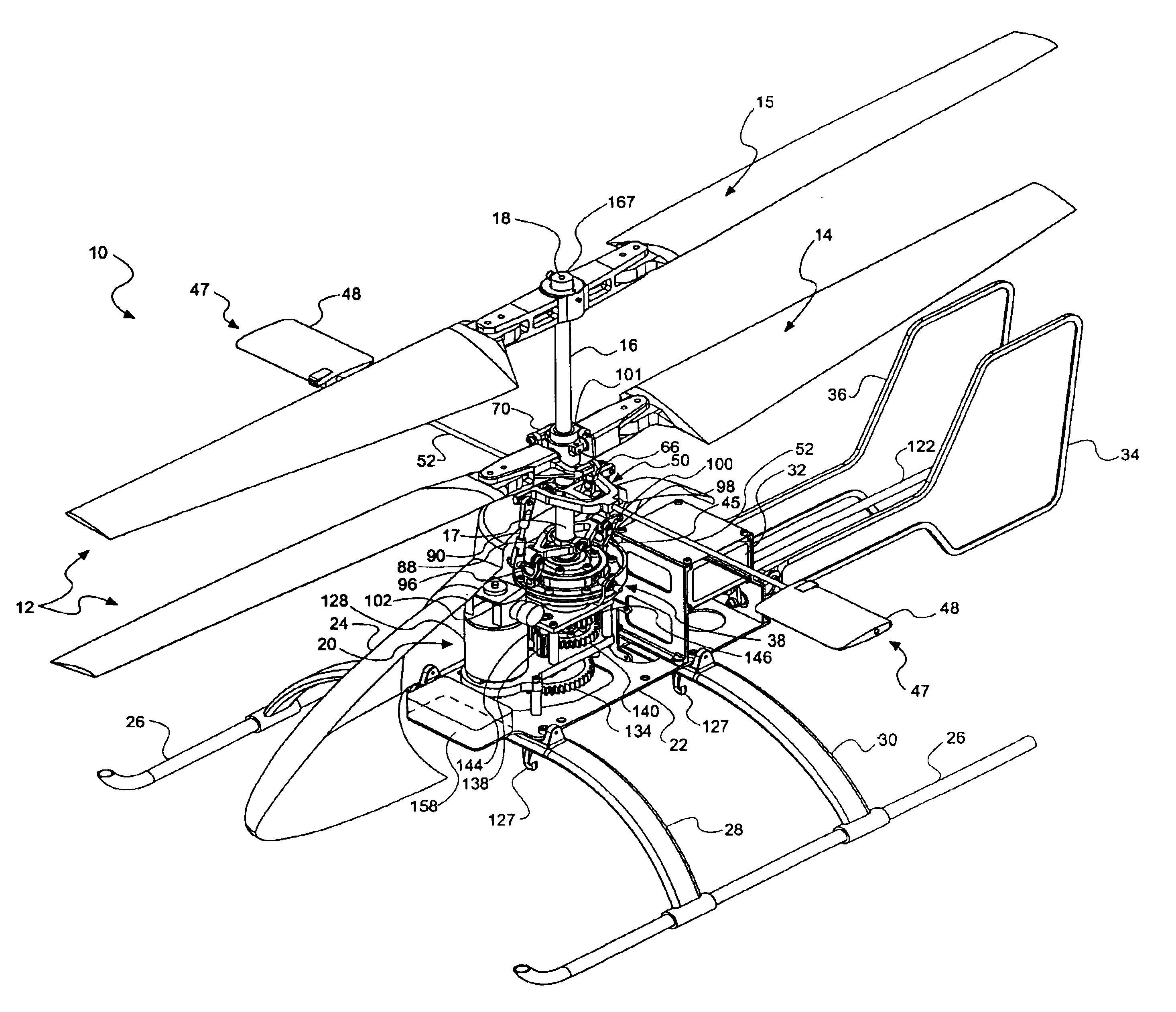
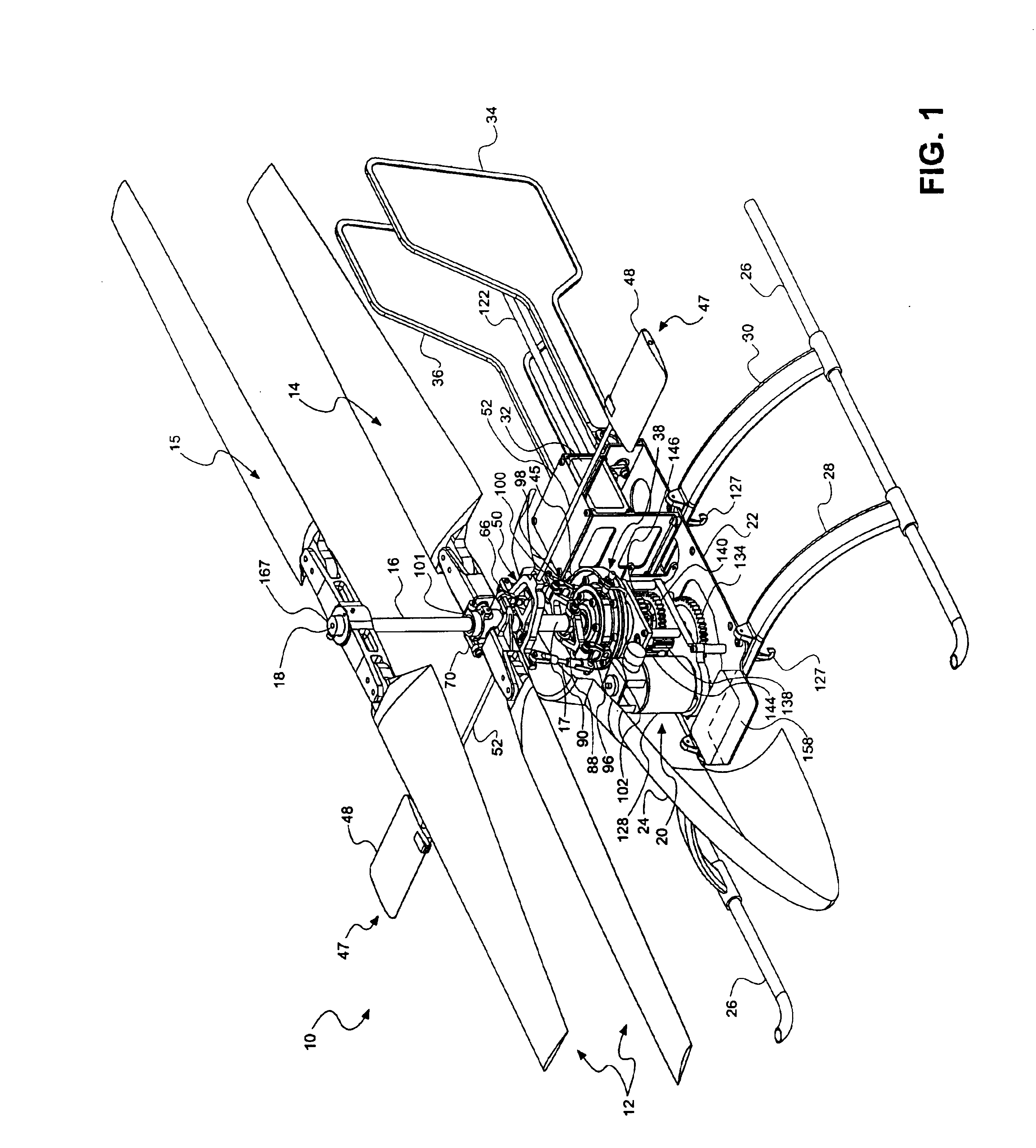
[0032]With reference to FIGS. 1, 2, 3 and 4 of the Drawings, which are provided by way of illustration, and not by way of limitation, the invention is embodied in a helicopter 10 comprising a coaxial rotor set 12 including a lower rotor 14 and an upper rotor 15 which are carried and actuated by an outer drive shaft 16 and an inner drive shaft 18, respectively. An outer tube 17 overlays the outer driveshaft, and will be further described below. The driveshafts are powered by a power assembly 20 carried by an airframe 22 comprising all supporting structure of the aircraft to which the various components are attached or are ultimately carried by.

[0033]The illustrated embodiment is a model helicopter 10, but as will be appreciated, the invention can be incorporated in larger aircraft. The model aircraft includes a canopy 24 which is supported by the airframe 22 and provides an outer covering for the helicopter, and which may be shaped and painted to resemble a full-sized helicopter. Th...


PUM


Abstract

A coaxial helicopter, comprising a first rotor carried by a first shaft and a second rotor carried by a second shaft; wherein one of the first and second rotors has cyclic pitch control and the other rotor does not have cyclic pitch control, at least pitch and roll control being implemented by cyclic blade pitch control of only one rotor of the coaxial rotor set. Provisions for yaw control can include differential collective control of the first and second rotors, providing yaw paddles and / or a tail rotor, ducted fan, or an air jet configured for yawing the coaxial helicopter.

Description

BACKGROUND[0001]1. Field of the Invention[0002]The invention relates to helicopter flight control systems. More particularly, the invention relates to a flight control system arrangement for a coaxial helicopter vehicle.[0003]2. Description of Related Art[0004]Coaxial helicopters have been known for many years. However, because of difficulties involved in the control of cyclic and collective pitch of rotor blades in a coaxial configuration, development of this type of aircraft has heretofore been limited. Conventional coaxial designs provide roll, pitch and yaw control by providing control input linkages for cyclic and collective pitch to both an upper rotor and a lower rotor of a coaxial rotor set. This has conventionally involved providing at least two swash plates; one below, and one above, the lower rotor, to transfer control inputs past the lower rotor to the upper rotor, which is rotating in the opposite direction.[0005]Several successful coaxial designs have been developed, f...

Claims


Application Information

Patent Timeline
Patent Type & Authority Patents(United States)
IPC IPC(8): B64C27/00B64C27/10
CPCB64C27/10
Inventor ROCK, EUGENE F.
Owner AEROTWIN MOTORS
Learn More