
Ergonomic trigger for a trigger sprayer

a technology of trigger sprayer and trigger, which is applied in the direction of single-unit apparatus, liquid transfer device, packaging, etc., can solve the problems of user's hand discomfort and the top finger of the user's hand discomfor

Inactive Publication Date: 2005-05-03
WESTROCK DISPENSING SYST
View PDF17 Cites 12 Cited by
  • Summary
  • Abstract
  • Description
  • Claims
  • Application Information

AI Technical Summary

Benefits of technology

[0008]The present invention overcomes the aforesaid disadvantages typically associated with prior art trigger sprayer triggers by providing an improved trigger having an ergonomic engagement surface that reduces the discomfort of the fingers of the user's hand during prolonged use of the trigger sprayer.
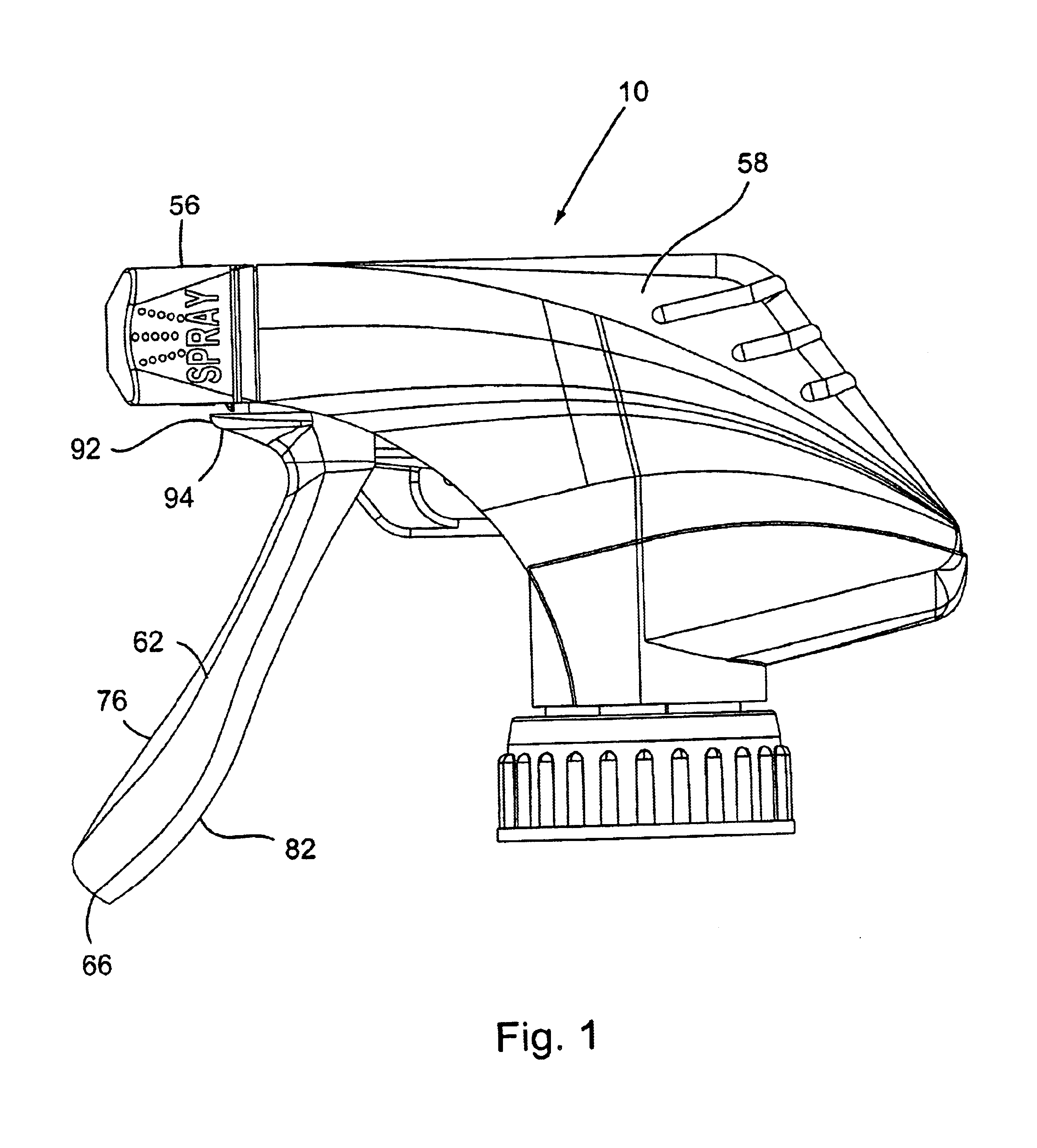
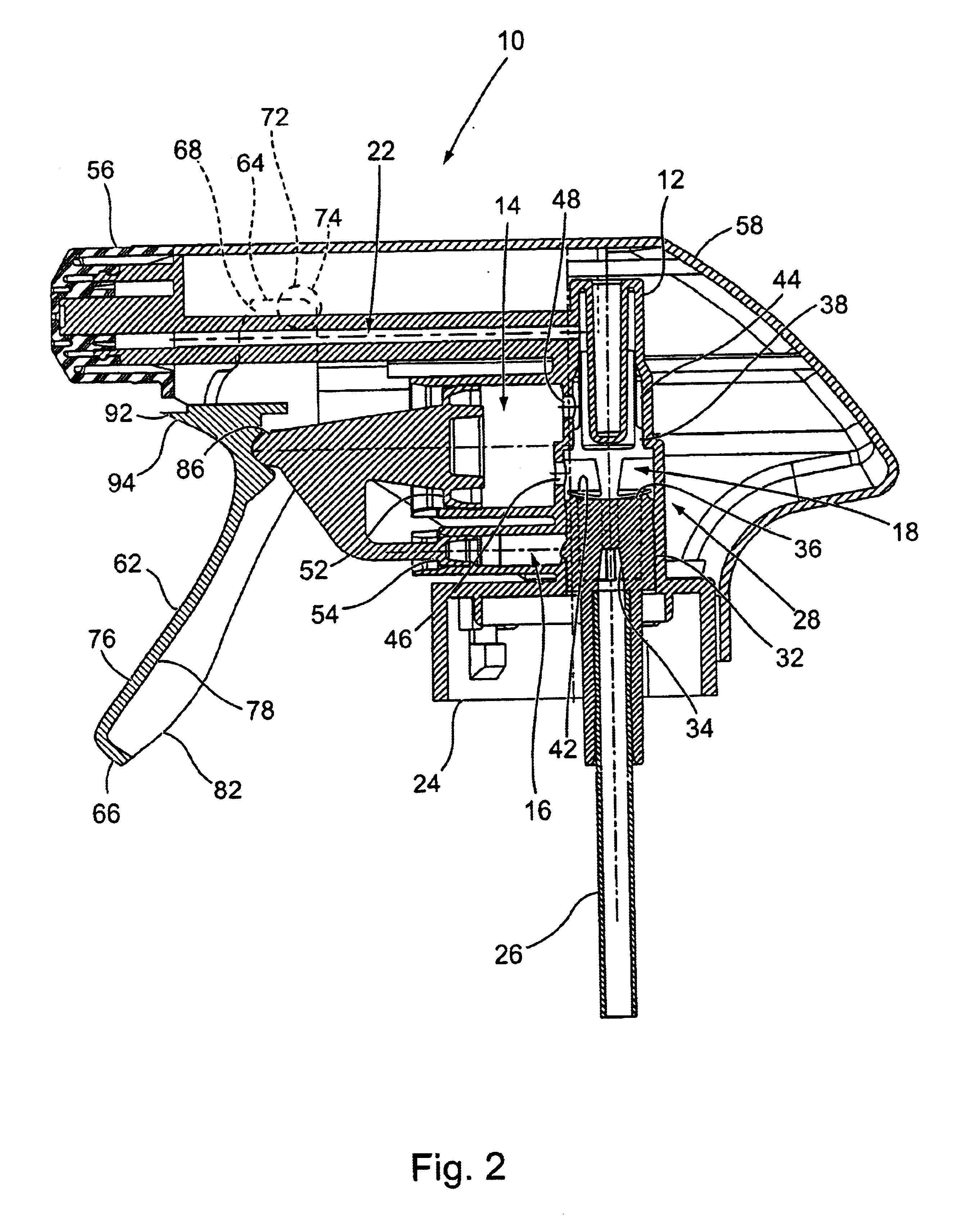
[0011]The improvement of the trigger of the invention is provided by a protrusion that projects outwardly from the trigger front surface. The protrusion is positioned on the trigger front surface adjacent and beneath the sprayer housing of the trigger sprayer. The finger engagement surface on the front of the trigger extends upwardly as a continuous curved surface that extends longitudinally along the front of the trigger and along a portion of the protrusion on the trigger. The portion of the finger engagement surface on the protrusion overhangs or projects outwardly from the trigger engagement surface on the front surface of the trigger. Thus, the portion of the finger engagement surface on the protrusion is positioned to extend over the upper finger of a user's hand holding the sprayer housing to manipulate the trigger relative to the trigger sprayer. The protrusion thereby prevents the upper finger of the user's hand from coming into contact with the trigger sprayer when the user's hand manipulates the trigger. In addition, the smooth continuous surface of the finger engagement surface on the front of the trigger and the portion of the finger engagement surface that extends across the protrusion comfortably supports the weight of the trigger sprayer and the attached liquid container on the top finger of the user's hand.

Problems solved by technology

The increase in the number of manual manipulations of the trigger on a trigger sprayer often results in discomfort to the user's hand due to the orientation of the trigger on the trigger sprayer.
This leads to discomfort of the top finger of the user's hand after repeated manipulations of the trigger sprayer trigger.

Method used


Image

  • Ergonomic trigger for a trigger sprayer
  • Ergonomic trigger for a trigger sprayer
  • Ergonomic trigger for a trigger sprayer

Examples


Embodiment Construction

[0022]The ergonomic trigger of the present invention is described herein as being employed on a manually operated liquid dispensing trigger sprayer of a particular construction. However, it should be understood that the ergonomic trigger of the invention may be employed on various different types of manually operated trigger sprayers and various different types of manually operated apparatus employing a trigger. Although the trigger of the invention is described as being employed with one particular construction of trigger sprayer, it should be understood that this explanation of the trigger of the invention is illustrative only and should not be interpreted as limiting the trigger for use with only one particular construction of trigger sprayer.

[0023]The trigger sprayer 10 of FIGS. 1 and 2 is similar to other prior art trigger sprayers in that it is basically comprised of a sprayer housing 12 that contains a pump chamber 14, a vent chamber 16, a liquid supply passage 18 and a liqui...


PUM


Abstract

A liquid dispensing, manually operated trigger sprayer has a trigger with an ergonomic finger engagement surface. The trigger finger engagement surface extends longitudinally across the front of the trigger and has a protrusion at the top of the surface. The protrusion has a finger engagement surface portion that rests on the top of a finger of a user's hand while the user's hand manipulates the trigger of the trigger sprayer.

Description

BACKGROUND OF THE INVENTION[0001](1) Field of the Invention[0002]The present invention pertains to a trigger sprayer apparatus of the type comprising a sprayer housing that is removably attached to a liquid container and has a dispensing nozzle and a manually operated trigger that is manipulated to draw liquid from the container and dispense the liquid from the dispensing nozzle as a spray, stream or foam. In particular, the present invention pertains to an ergonomic trigger for a trigger sprayer. The trigger has a finger engagement surface extending upwardly across the front of the trigger and a protrusion at the top of the trigger that has a finger engagement surface portion that comfortably rests on the top of a finger of the hand of a user of the trigger sprayer.[0003](2) Description of the Related Art[0004]In prior art trigger sprayers employed in dispensing liquid from liquid containers attached to the trigger sprayers, the typical trigger sprayer is comprised of a sprayer hou...

Claims


Application Information

Patent Timeline
IPC IPC(8): B05B11/00
CPCB05B11/3011B05B11/1011
Inventor FOSTER, DONALD D.STARK, JEFFREY P.
Owner WESTROCK DISPENSING SYST
Learn More