
Camera, device for capturing object image, automatic focus adjusting system and method for adjusting automatic focus for the same

a technology for capturing objects and automatic focus, which is applied in the direction of camera focusing arrangement, printers, instruments, etc., can solve the problems of discontinuous evaluating value for af, adverse effect on evaluating value for af, and discontinuous evaluating value of one part so as to increase the efficiency of the focus adjusting scan and improve the reliability of the focus adjusting operation.

Inactive Publication Date: 2005-04-26
RICOH KK
View PDF4 Cites 95 Cited by
  • Summary
  • Abstract
  • Description
  • Claims
  • Application Information

AI Technical Summary

Benefits of technology

[0029]In this regard the present invention is made in view of the above described situation and one object of the present invention is to provide camera, device for capturing object image, an automatic focus adjusting system and a method for adjusting automatic focus for the same, by which operations related to a focus adjusting scan are regulated to suppress a useless action, and efficiency and reliability of the focus adjusting scan can be effectively improved.
[0030]Another object of the present invention is to provide a camera by which operations related to a focus adjusting scan are regulated to suppress a useless action, and efficiency and reliability of the focus adjusting scan can be effectively improved when the focus adjusting is continuously performed again and again for the same object to be photographed in almost in the same situation.
[0031]Other object of the present invention is to provide a camera by which an efficiency of focus adjusting scan can be more highly improved.

Problems solved by technology

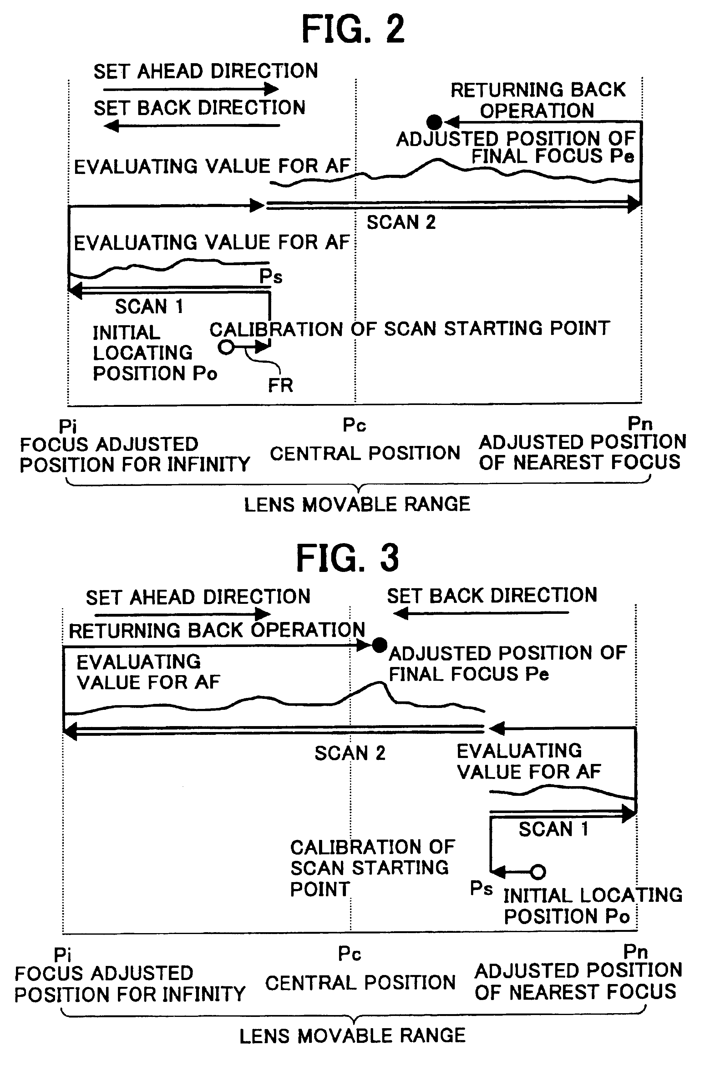
However there are some problems in the operation “focus adjusting operation is initiated from the initial locating position Po” depicted in FIG. 18 to FIG. 20 based on the Japanese Patent Laid Open Publication No.
Accordingly this method has a problem that “is there any adverse effect to performance characteristics by one part of the focus adjusting scan becomes discontinuous?”.
In the matter of fact because the evaluating value for AF obtained time has a discrepancy at the discontinuing point of the focus adjusting scan, there is an anxiety that evaluating value for AF becomes also discontinuous, in addition because the directions of focus adjusting scan at the scan discontinued point are different, there is a possibility that the dependence of scanning direction may cause some adverse effect on the evaluating value for AF.
To make matters worse not only overlapping between the sum discontinuing point and the initial locating position Po, but in many case the initial locating position Po also overlaps with the last focus adjusted position, because of this it has a problem that a discontinuity of focus adjusting scan occurs at a position which has the highest probability of focus adjusted position existence and thereby accuracy of peak detection is decreased in certain extent when the continuous photographing of the same object to be photographed is considered.
Hei 05-241066 still has a kind of problem when it is thought from the above describe view point.
Hei 05-241066, undesirable situation is also caused by in a case when the initial locating position Po is located near to the end points of the scanning range.
As a result of this fact, because the focus adjusting operation is moved inevitably to the second focus adjusting scan (scan 2), the effect of speeding up of automatic focus adjusting operation is lost and only decreasing of accuracy of focus adjusting operation caused by an existence of the scan discontinuous point, is remained.
That is to say in a case when an enough strength of scan cannot be ensured to discriminate a peak position as the first focus adjusting scan (scan 1), it makes effective speeding up of automatic focus adjusting operation difficult.

Method used


Image

  • Camera, device for capturing object image, automatic focus adjusting system and method for adjusting automatic focus for the same
  • Camera, device for capturing object image, automatic focus adjusting system and method for adjusting automatic focus for the same
  • Camera, device for capturing object image, automatic focus adjusting system and method for adjusting automatic focus for the same

Examples


Embodiment Construction

[0099]Hereinafter detailed explanation will be given on camera, a device for capturing object image, an automatic focus adjusting system and a method for adjusting automatic focus in accordance with the present invention on basis of embodiment with reference to the accompanying drawings.

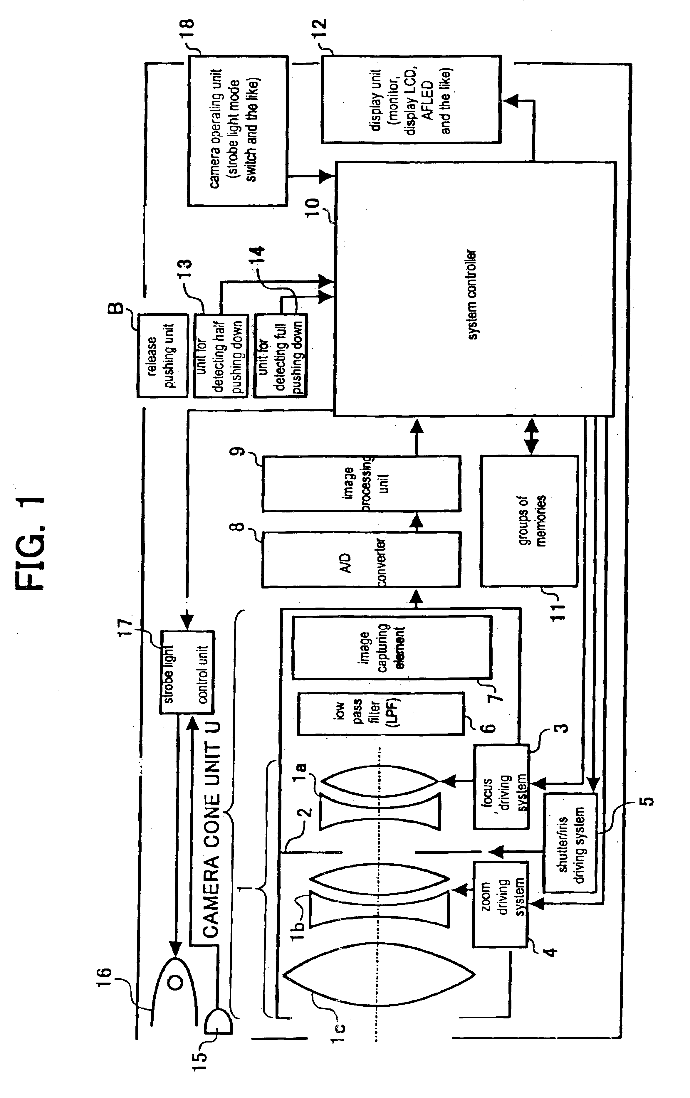
[0100]A camera depicted in FIG. 1 includes an optical system 1, a shutter / iris unit 2, a focus driving system 3, a zoom driving system 4, a shutter / iris driving unit 5, a low pass filter (LPF) 6, an image capturing element 7, an A / D (analog-digital) converter 8, an image processing unit 9, a system controller 10, a group of memories 11, a display unit 12, a unit for detecting half pushing down 13, a unit for detecting full pushing down 14, a light receiving unit 15, a strobe light radiating unit 16, a strobe light control unit 17, a camera operating unit 18 and a release button pushing unit 19.

[0101]In FIG. 1 light from an object to be photographed is brought into the optical system 1 as a photograph...


PUM


Abstract

System controller (10) seeks a focus adjusting evaluating value which is indicative of focus adjusting state as a criterion from object image information, and searches a focus adjusted position where focus adjusting evaluating value becomes the most appropriate and drives the focus operating means to the focus adjusted position to perform a focus adjusting by a focus adjusting scan to obtain a plurality of focus adjusting evaluating value by operating the focus adjusting evaluating value detecting means while driving focusing lens (1a) in at lease one way of continuous way or intermittent way which varies focus adjusting state of the object image.System controller (10) shifts a scan starting point from an initial locating position Po of the focusing lens (1a) in a first predetermined amount of distance in a predetermined direction then initiate scan from the initial locating position toward an opposite direction to the predetermined direction.

Description

BACKGROUND OF THE INVENTION[0001]1. Field of the Invention[0002]The present invention relates to an automatic focus adjusting (hereinafter it is referred to also as “AF”) system which is so called auto focus adjusting system or auto focus system, and more particularly, this invention relates to an automatic focus adjusting system and a method for adjusting automatic focus capable of focus adjusting by focus adjusting scanning in that focus adjusting state of an object image is varied, an evaluating value of focus adjusting which is indicative of focus adjusting state as a criterion is sought from object image information corresponding to the object image, the focus adjusting state is varied continuously or intermittently and a plurality of the evaluating values are obtained such that a focus adjusting state is searched in which the evaluating value of focus adjusting is the most appropriate, and relates to camera which utilizes the system and the method, an image input device includ...

Claims


Application Information

Patent Timeline
IPC IPC(8): G02B7/28G02B7/08G03B13/36G02B7/36H04N5/232
CPCH04N5/23212G02B7/28H04N23/67
Inventor SHINOHARA, JUNICHI
Owner RICOH KK
Learn More