Eureka AIR delivers breakthrough ideas for toughest innovation challenges, trusted by R&D personnel around the world.

Rain gutter cover system

Inactive Publication Date: 2005-04-26
SEISE JR JOHN W
View PDF9 Cites 64 Cited by
  • Summary
  • Abstract
  • Description
  • Claims
  • Application Information

AI Technical Summary

Benefits of technology

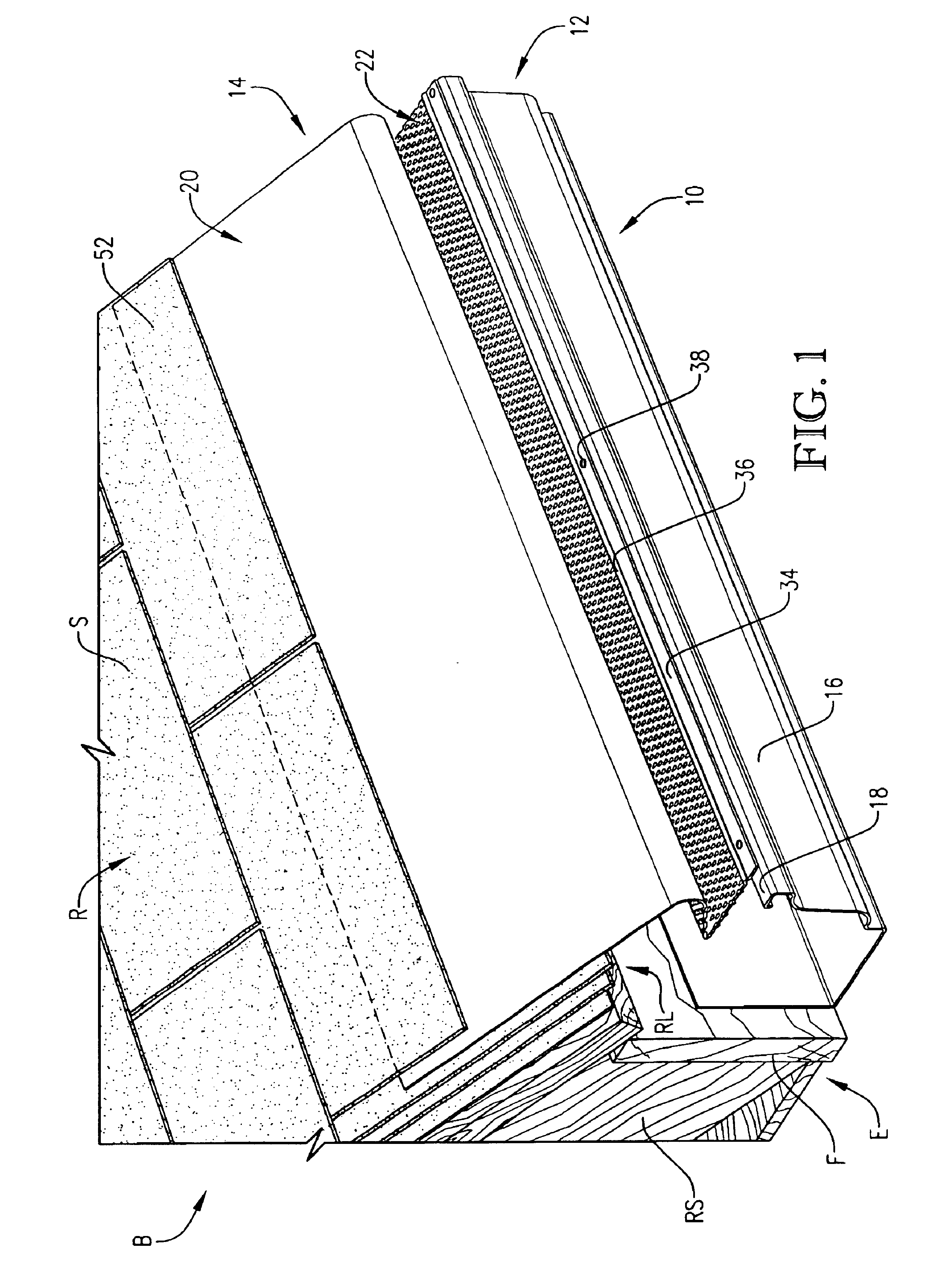
[0006]The present invention provides an improved rain gutter cover system that does not suffer from the problems and limitations of the prior art cover systems detailed above. The inventive cover system provides a plurality of unique fluted perforations that effectively siphon large amounts of water into the gutter yet are configured to substantially prevent undesired debris from entering the gutter. In a preferred embodiment, the fluted perforations are the only means of water entering the guttering system and are all guarded by bull-nosed ledges adjacent the roofline, as well as a plurality of ledges running transverse along the valleys of the roof.
[0007]A first aspect of the present invention concerns a rain gutter cover system for directing water running off a building's roof into a gutter extending along the roofline while simultaneously preventing undesired debris from entering the gutter. The system broadly includes a screen adapted to couple to the gutter and being operable to extend from the roofline over the gutter in a covering relationship when the screen is coupled to the gutter so that substantially all water entering the gutter must pass through the screen. The screen includes at least one section sloping downhill between the roofline and the gutter. The screen includes a plurality of perforations formed therein for siphoning water through the screen and into the gutter. The perforations comprise the only means for water to pass through the screen. Each perforation includes a channel formed in the screen adjacent the perforation on the uphill side of the perforation for channeling water into the perforation. At least a portion of the plurality of perforations are formed in the at least one section.
[0008]A second aspect of the present invention concerns a valley cover system for directing water running along a trough formed between two slopes in a building's roof wherein the trough extends from a ridge to a roofline and wherein the cover

Problems solved by technology

However, these prior art guttering systems are undesirably prone to collecting undesired debris such as foliage, trash, animal excrement and remains, toys, etc.
Debris accumulation can become built up to the point that the guttering system no longer adequately drains water.
Debris accumulation is also particularly problematic in gutters under a valley in the roof (e.g., where two differing slopes intersect, etc.) because the valleys tend to collect debris and drain it into the gutter below the valley.
As a result, water undesirably accumulates in the gutters where it can run over the sides to an unwanted location, leak into the building, cause rot and / or rust damage to the building and / or guttering, and / or overload the gutters thereby pulling the gutters out of a proper working orientation.
These prior art cover systems are problematic and suffer from several undesirable limitations.
For example, the prior art screens are particularly susceptible to debris becoming lodged in the grid openings, which in turn accumulates further debris thus compromising the ability of water to sufficiently drain into the guttering system.
The prior art covers enable smaller debris to enter the guttering system, which in turn can accumulate in the gutters and down spouts thereby clogging the guttering system.
Additionally, these prior art cover systems are particularly susceptible to animals building nests in and around the cover systems thereby undermining the systems' efficacy.
Furthermore, heretofore, none of the prior art cover systems have addressed the problem of relatively large debris accumulation in and around the valleys in a roof, and even the most effective prior art cover systems become compromised by heavy debris accumulation beneath a valley.

Method used


Image

  • Rain gutter cover system
  • Rain gutter cover system
  • Rain gutter cover system

Examples


Embodiment Construction

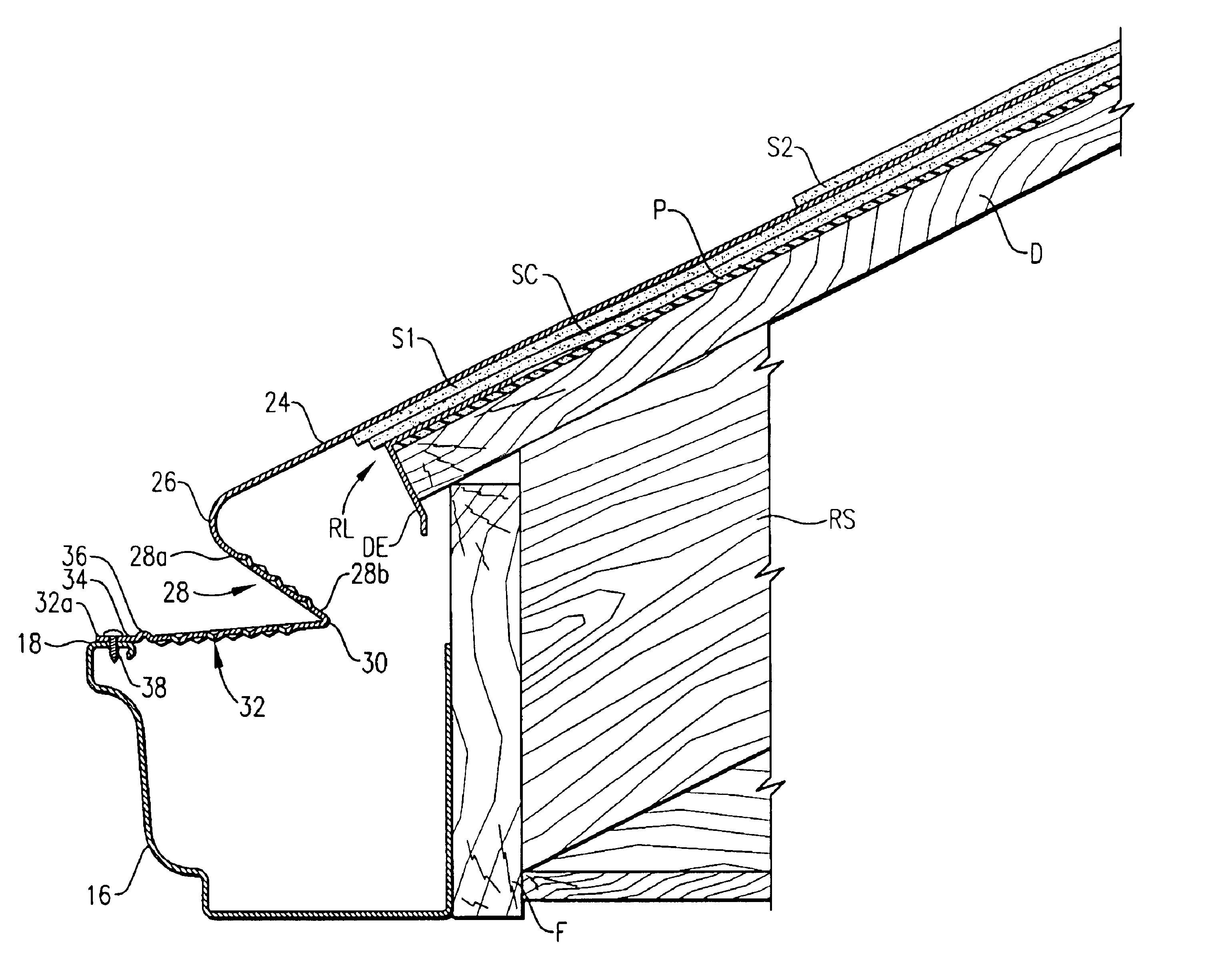
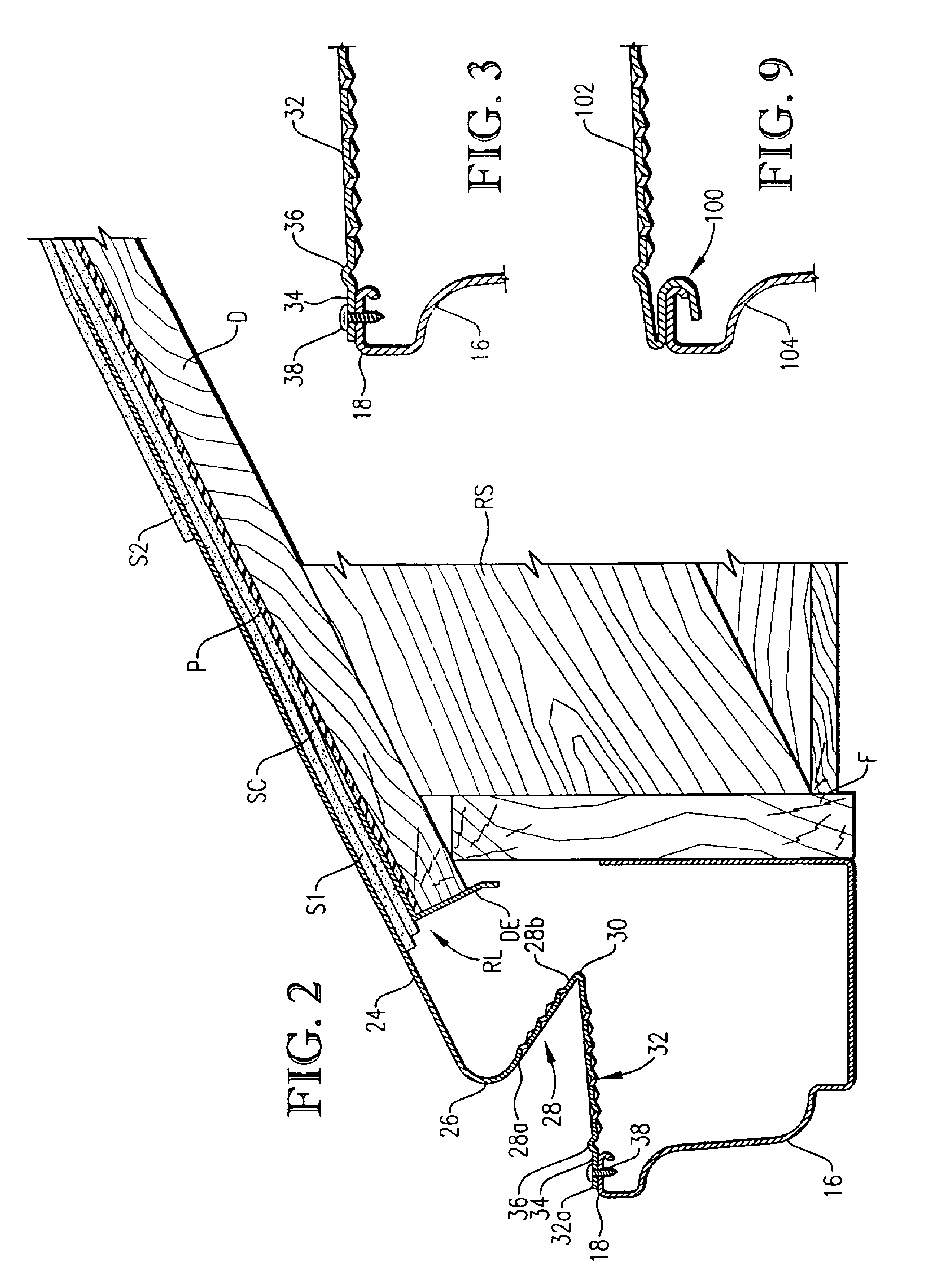
[0021]FIG. 1 illustrates a segment of a rain gutter cover system 10 constructed in accordance with the principles of a preferred embodiment of the present invention and configured for directably collecting rain water running off of the roof R of a building B while substantially preventing undesired debris from entering the gutter. The illustrated system 10 is shown affixed to a conventional composite roof commonly utilized on residential houses. In one manner well known in the art, the illustrated building B presents a plurality of sloping rafters RS that define an eave E overhanging an exterior wall (not shown). A fascia board F is coupled along the lower-most ends of the rafters RS. The roof R of the building B is supported on the sloping rafters RS and includes a layer of decking D, a layer of tar paper P, a drip edge DE, and overlapping courses of shingles S—including a starter course SC, a first course of shingles S1, and a second course of shingles S2 (see FIGS. 1 and 2). The ...


PUM

PropertyMeasurementUnit
Angleaaaaaaaaaa
Diameteraaaaaaaaaa

Abstract

A rain gutter cover system (10) constructed in accordance with the principles of a preferred embodiment of the present invention is disclosed. The system (10) is configured for directably collecting rain water running off of the roof (R) of a building (B) while substantially preventing undesired debris from entering the gutter (16). The system (10) broadly includes a gutter assembly (12) and a cover assembly (14) coupled to, and covering, the gutter assembly (12). The cover assembly (14) includes a one piece screen (20) and a plurality of fluted perforations (22) formed in the screen (20). The fluted perforations (22) are each particularly configured to draw water through the screen (20) without allowing undesired debris through the screen (20) and each includes a channel (40) recessed into the screen (20) and a corresponding hole (42) defined in the downhill end of the channel (40). A valley segment (210) of the system is also disclosed and includes a plurality of bull-nose ledges (212, 214, 216, 218 and 220), each guarding a plurality of fluted perforations (222) along the valley of a roof.

Description

BACKGROUND OF THE INVENTION[0001]1. Field of the Invention[0002]The present invention relates generally to guttering systems for collecting rain water running off a building's roof and directing the water away from the roof. More specifically, the present invention concerns a rain gutter cover system that enables the gutter to collect and direct the rain water while simultaneously preventing undesired debris from entering the gutter. The inventive cover system includes a plurality of unique fluted perforations for siphoning water through the system and into the gutter while screening out debris. In a preferred embodiment, the cover system includes a plurality of bull-nosed ledges that guard the fluted perforations, including a ledge running adjacent the roofline, as well as a plurality of ledges running transverse along the valleys of the roof.[0003]2. Discussion of Prior Art[0004]Gutters for collecting rain water running off of a roof are known in the art. These gutters are typical...

Claims


Application Information

Patent Timeline
IPC IPC(8): E04D13/076E04D13/04
CPCE04D13/076
Inventor SEISE, JR., JOHN W.
Owner SEISE JR JOHN W
Why Eureka
Eureka Blog
Learn More