Multi-stage EDM filter

a filter and multi-stage technology, applied in the direction of moving filter element filters, filtration separation, separation processes, etc., can solve the problems of not being able to precisely install equipment on the assembly line of filters featuring rapidity, requiring close assembly tolerances, unduly complicated relief valve assemblies, etc., to achieve easy manufacturing, avoid extra costs, and increase the useful life of edm filters

Inactive Publication Date: 2005-04-19
HOFF ENG
View PDF11 Cites 9 Cited by
  • Summary
  • Abstract
  • Description
  • Claims
  • Application Information

AI Technical Summary

Benefits of technology

[0019]According to an alternative embodiment, a pressure-operated arrangement is provided whereby the inner filter element moves relative to the outer filter element when a predetermined pressure is reached due to the entrapment of contaminants by the inner filter, thereby allowing the fluid to be filtered to flow past the inner filter and through the outer filter. As a further alternative, the construction of the inner filter element may be such that it tears, decomposes, or disintegrates when a predetermined pressure is reached due to the entrapment of contaminants by the inner filter, thereby allowing the fluid to be filtered to flow past or through the inner filter and through the outer filter.
[0021]The advantages of the invention include an increase in an EDM filter's useful service life, achieved by utilizing the available internal volume of commonly used EDM filters. No filter of larger cubic footage is required. The concept incorporates the advantages of the externally plumbed EDM inside-out filters without disturbing the existent plumbing and tank arrangements, thus avoiding the extra costs associated with plumbing fixtures external to the filter. The extra filter service life occurs in a consistent and reproducible manner, and the design of the valving device is simple, straight forward, and easy to manufacture.

Problems solved by technology

Similarly, relief valve assemblies can be unduly complicated, require close assembly tolerances, and are not easily installed on filter assembly lines featuring rapidity without precise installation equipment.
The sludgy inside of a working EDM filter would be a challenging environment for any mechanical valving device.
1) the additional fixtures: a male plug 45 or nozzle on the filter itself, a female coupling device 47 on the hose, a hose clamp and hose 49, shown in FIG.
2) a new filter tank or housing that accommodates the operator's need to access the coupling.
3) the additional facility space required for the plumbing fixtures and the change-out operation just mentioned

Method used


Image

  • Multi-stage EDM filter
  • Multi-stage EDM filter
  • Multi-stage EDM filter

Examples


Embodiment Construction

[0034]For the purpose of understanding the invention, reference will now be made to the embodiment illustrated in the drawings. It should be understood that no limitations of the invention's scope is thereby intended. The specification relates primarily to filtering the common conductive EDM fluids deionized water and dielectric oil but its principles could be extended to include other flowable substance including, but not limited to, machining fluids, coolants, other industrial and process fluids, as well as air, gases, and vapors. Further applications of the principles of the invention as illustrated would normally occur to one skilled in the art to which the invention relates.

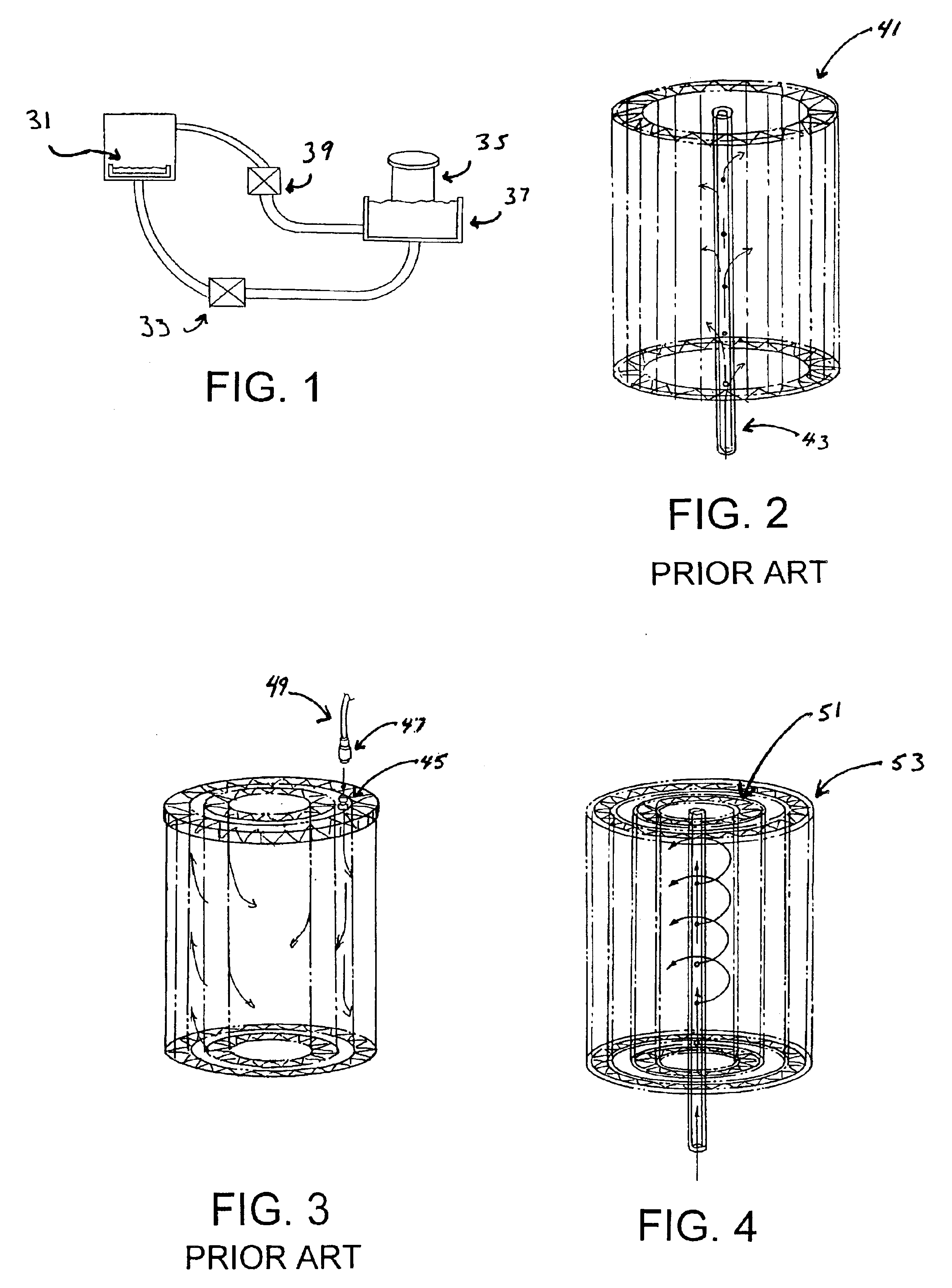
[0035]The design of a common, commercially available EDM filter was illustrated previously in FIG. 3. This filter has two concentric cylinders of pleated filter paper intended to filter the dirty fluid in the inside-out plumbing configuration. It is the more economical incorporation of the inner cylinder, wi...


PUM

PropertyMeasurementUnit
thicknessaaaaaaaaaa
pressureaaaaaaaaaa
viscosityaaaaaaaaaa

Abstract

A two-stage, retrofit filter is adapted for use with an electrical discharge machine (EDM) includes nested inner and outer filtering elements that may be placed as a unit in the same tank and over the apertured standpipe used for a one-stage filter, such that the fluid to be filtered now flows through each of the multiple filter elements. The retrofit EDM filter may be configured for flow in either direction, though the usual arrangement is one whereby the fluid being filtered flows up through the bottom of the tank, out the apertured standpipe, and into the inner filter element. Preferably, the filter elements are cylindrical, pleated elements composed of a technical grade filter paper. In the preferred embodiment, a pressure-operated release valve is provided in conjunction with the inner filter, such that when a predetermined pressure is reached due to the entrapment of contaminants by the inner filter, the valve opens to allow the fluid to be filtered to flow through the outer filter.

Description

FIELD OF THE INVENTION[0001]This invention relates generally to filters and fluid control devices. More particularly, it relates to a retrofit filter for electrical discharge machines incorporating additional filtration elements.BACKGROUND OF THE INVENTIONSpin-On Filters and EDM Filters[0002]Prior art discloses various valves to direct the flow of dirty fluid inside a filter in a variety of applications including hydraulic, fuel, and engine lubrication systems. In automotive spin-on oil filters, for example, pressure relief valves are designed to provide circulating engine oil a by-pass route when the filter is restricted due to dirt accumulation or high oil viscosity because of a cold start in a winter climate. Some examples of known designs can be found in U.S. Pat. No. 4,127,484 (Walulik et al.), U.S. Pat. No. 5,584,987 (Mules), U.S. Pat. No. 5,690,816 (Covington), and U.S. Pat. No. 6,096,199 (Covington). These filters have the now familiar design of a casing enclosing a cylinder...

Claims


Application Information

Patent Timeline
Patent Type & Authority Patents(United States)
IPC IPC(8): B01D29/23B01D29/13B01D35/147B01D35/14
CPCB01D29/232B01D35/147B01D29/58
Inventor DOYLE, E. MICHAELDOYLE, EDWARD M.
Owner HOFF ENG
Why Eureka
Try Eureka