
Brake drum and method for producing the same

a technology of brake drums and drums, applied in the direction of brake discs, brake drums, friction linings, etc., can solve the problems of reducing the desired weight of motorcycles or automobiles to which the brake drums are applied, and achieve the effect of increasing efficiency

Inactive Publication Date: 2005-04-19
HONDA MOTOR CO LTD
View PDF14 Cites 58 Cited by
  • Summary
  • Abstract
  • Description
  • Claims
  • Application Information

AI Technical Summary

Benefits of technology

[0006]It is therefore an object of the present invention to provide a lightweight brake drum and a method which can produce a lightweight brake drum with increased efficiency.

Problems solved by technology

In general, the traditional brake drums are formed integrally, or in one piece, of cast iron in order to retain a necessary strength of the frictional surface; however, the traditional cast-iron brake drums are heavy in weight and thus would hinder desired weight reduction of the motorcycles or automobiles to which the brake drums are applied.

Method used


Image

  • Brake drum and method for producing the same
  • Brake drum and method for producing the same
  • Brake drum and method for producing the same

Examples


Embodiment Construction

[0033]Preferred embodiments of the present invention will be described in detail hereinbelow with reference to the accompanying drawings.

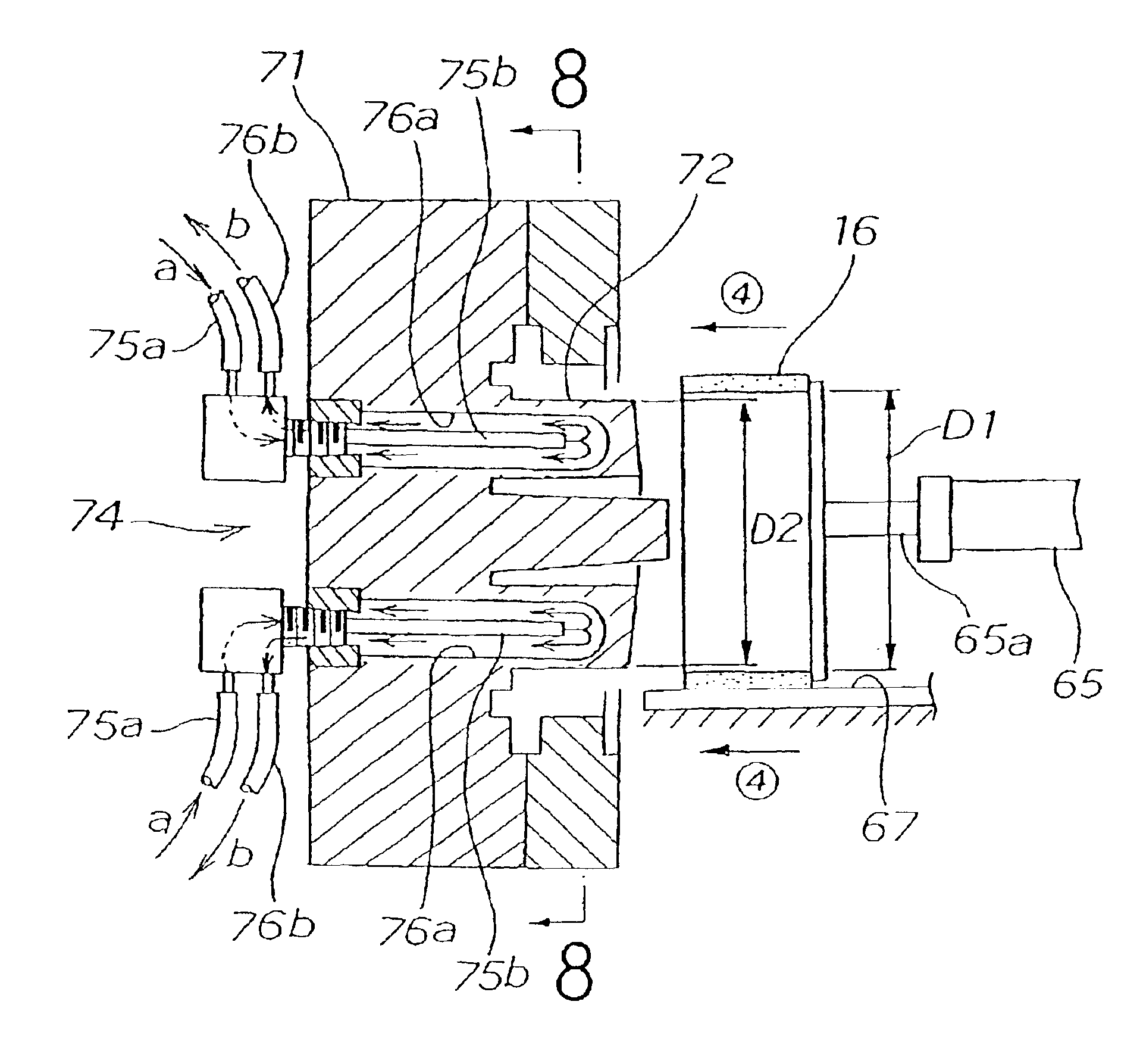
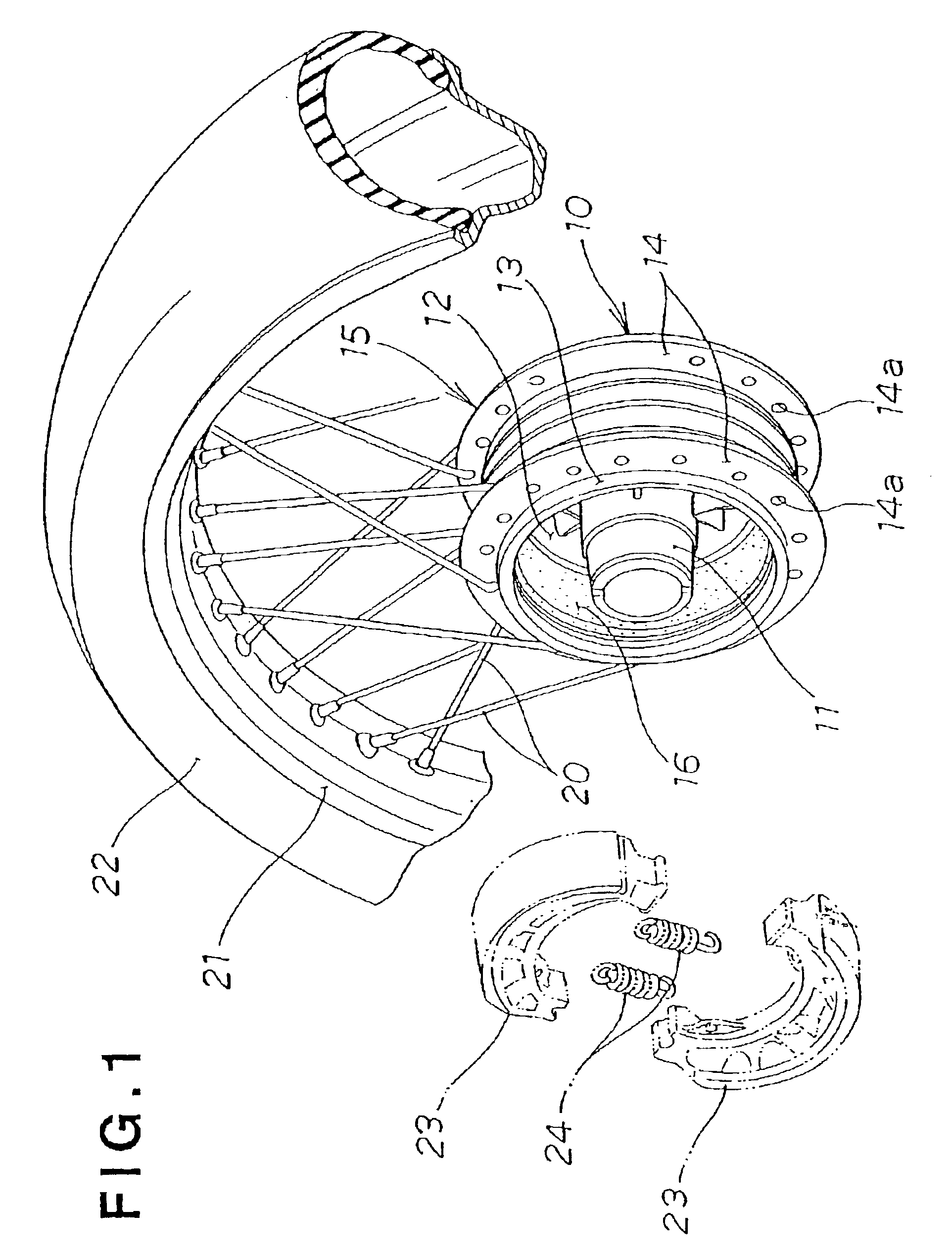
[0034]In FIG. 1, there is shown a brake drum 10 in accordance with the present invention, which includes a boss 11 for mounting on a rear or front axle shaft, a flange 12 integrally formed at the right end of the boss 11, a drum body (i.e., backup member) 13 integrally formed on and around the outer periphery of the flange 12, and an annular friction member 16 secured to the inner circumferential surface of the drum body 13. A pair of opposed flanges 14 are secured to and around the outer periphery of the drum body 13.

[0035]The above-mentioned boss 11, flange 12, drum body 13 and pair of opposed flanges 14 are integrally formed by casting of an Al alloy, to thereby together constitute a one-piece hub 15. The hub 15 thus formed of the Al alloy can be significantly reduced in weight.

[0036]The friction member 16 is formed of an aluminum-base composite...


PUM

PropertyMeasurementUnit
pitch angleaaaaaaaaaa
temperatureaaaaaaaaaa

Abstract

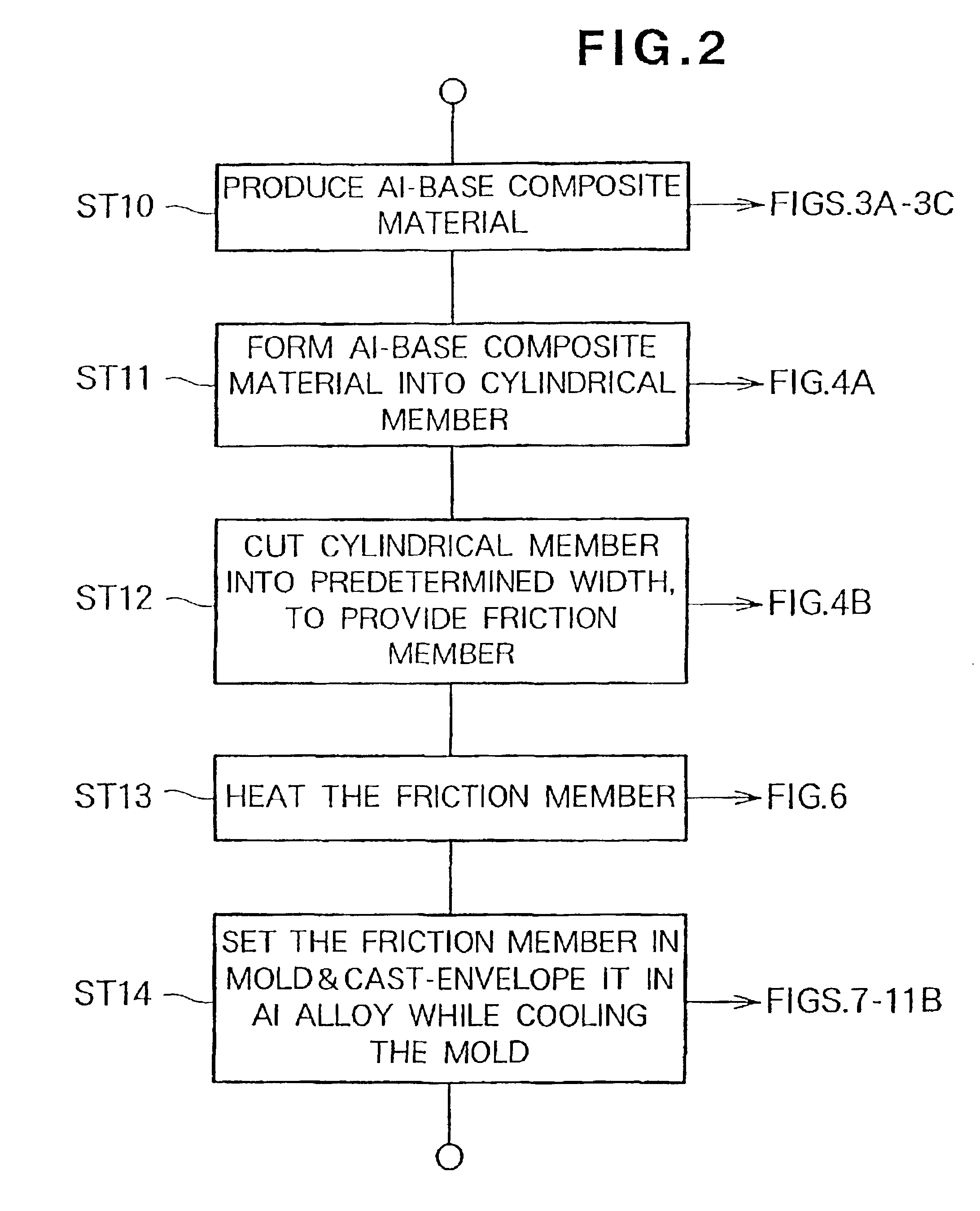
A brake drum includes a ring-shaped drum body (13), and a friction member (16) secured to the inner circumferential surface (18) of the drum body. Because the drum body is formed of a lightweight Al alloy and the friction member is formed of an Al-base composite material, the brake drum can be reduced in weight as a whole. Further, because the friction member, having projecting portions (17a) formed on its outer periphery (17), is cast-enveloped by molten metal of the Al alloy, the friction member and the drum body can be firmly fastened together. Thus, even when a great braking force is applied to the drum brake, the friction member can be prevented from being undesirably detached from the drum body.

Description

TECHNICAL FIELD[0001]The present invention relates generally to brake drums for use in motorcycles or automobiles and methods for producing such brake drums, and more particularly to a brake-drum producing method in accordance with which a friction member of the brake drum is formed of an aluminum-base composite material and then the friction member is cast-enveloped by an aluminum alloy.BACKGROUND ART[0002]Some of the motorcycles or automobiles known today use a drum brake apparatus as their braking apparatus. In the drum brake apparatus, brake shoes are pressed against the inner circumferential surface (frictional surface) of a brake drum rotating with a vehicle wheel to thereby control the rotation of the brake drum.[0003]In general, the traditional brake drums are formed integrally, or in one piece, of cast iron in order to retain a necessary strength of the frictional surface; however, the traditional cast-iron brake drums are heavy in weight and thus would hinder desired weigh...

Claims


Application Information

Patent Timeline
Patent Type & Authority Patents(United States)
IPC IPC(8): C22C1/10F16D65/12F16D65/02F16D69/00F16D65/10F16D69/04
CPCC22C1/1036F16D65/10F16D65/12F16D69/0416B21C23/08B22F2998/10F16D2250/0092F16D2250/0015C22C2001/1057F16D2065/132F16D2065/1356F16D2069/0441F16D2069/0483F16D2200/003F16D2200/0039F16D2200/006F16D2250/00F16D2250/0007C22C1/1057
Inventor KOIZUMI, TAKASHIECHIGO, TAKAHARUSHOJI, HIROTONAKAO, YASUHIROSUGAYA, KUNITOSHI
Owner HONDA MOTOR CO LTD
Learn More