
Power control apparatus, and associated method, for a sending station of a communication system

a communication system and power control technology, applied in power management, substation equipment, wireless communication, etc., can solve the problems of difficult matching of reference signals having the same amplitude modulated component corresponding to the output power levels of edge modulated signals with detected output signals, and preventing the change of power levels of transmit signals

Inactive Publication Date: 2005-04-12
NOKIA CORP
View PDF4 Cites 16 Cited by
  • Summary
  • Abstract
  • Description
  • Claims
  • Application Information

AI Technical Summary

Benefits of technology

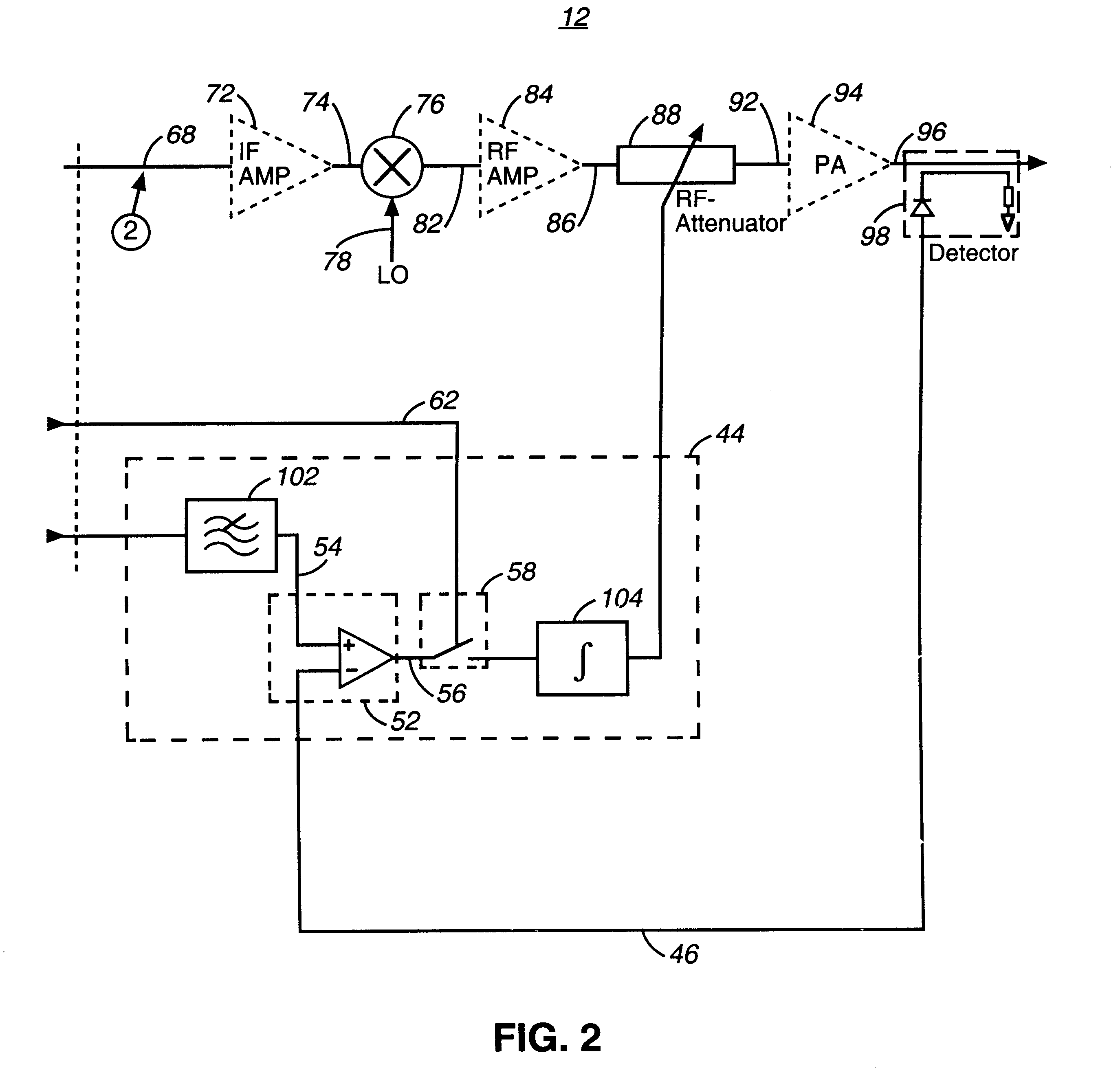
In one aspect of the present invention, changes in the power levels of a transmit signal are permitted when closed-loop power control measurements is done on nonamplitude-modulated component portions of the signal. And, changes in power levels of the transmit signal are prevented by open-loop power control on amplitude-modulated component portions of the signal.

Problems solved by technology

Because a wireline connection is not required to be formed between the sending and receiving stations to permit the communication of information therebetween, communications are permitted at, and between, locations at which formation of a wireline connection would not be possible.
When a conventional, GSM power control scheme is utilized to control the power levels at which an EDGE-modulated signal is transmitted, the amplitude modulation interferes with power-control operations.
That is to say, a reference signal having the same amplitude modulated component corresponding to the output power levels of the EDGE modulated signal is difficult to match with the detected output signal due to delays and non-linearity associated with formation of the final, output signal at the base transceiver station.
As the level of both the reference signal and the output signal subsequent to amplification are unlikely to be identical, the output power levels of output signals generated at the sending station is susceptible to drift due to the inaccuracy of the loop.

Method used


Image

  • Power control apparatus, and associated method, for a sending station of a communication system
  • Power control apparatus, and associated method, for a sending station of a communication system
  • Power control apparatus, and associated method, for a sending station of a communication system

Examples


Embodiment Construction

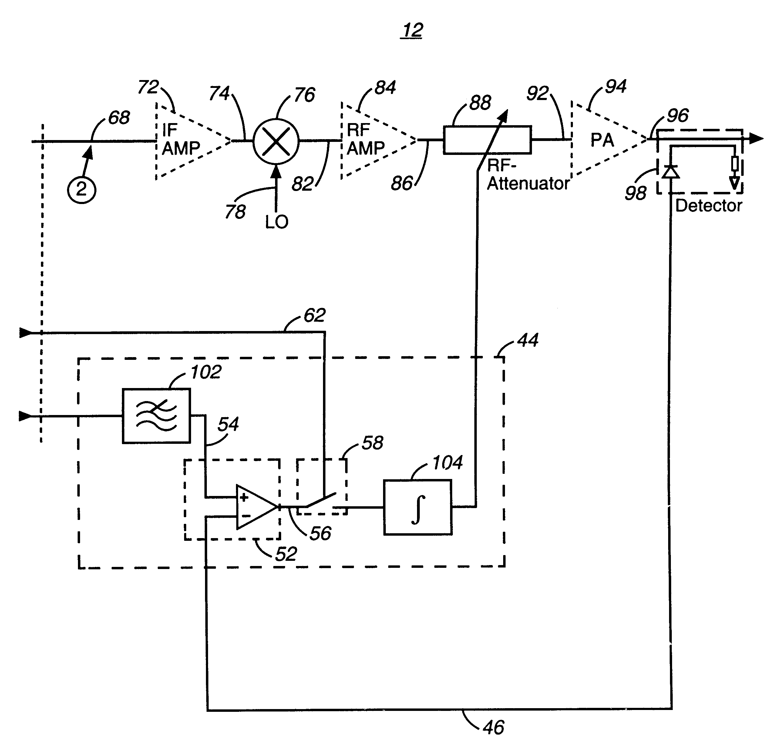
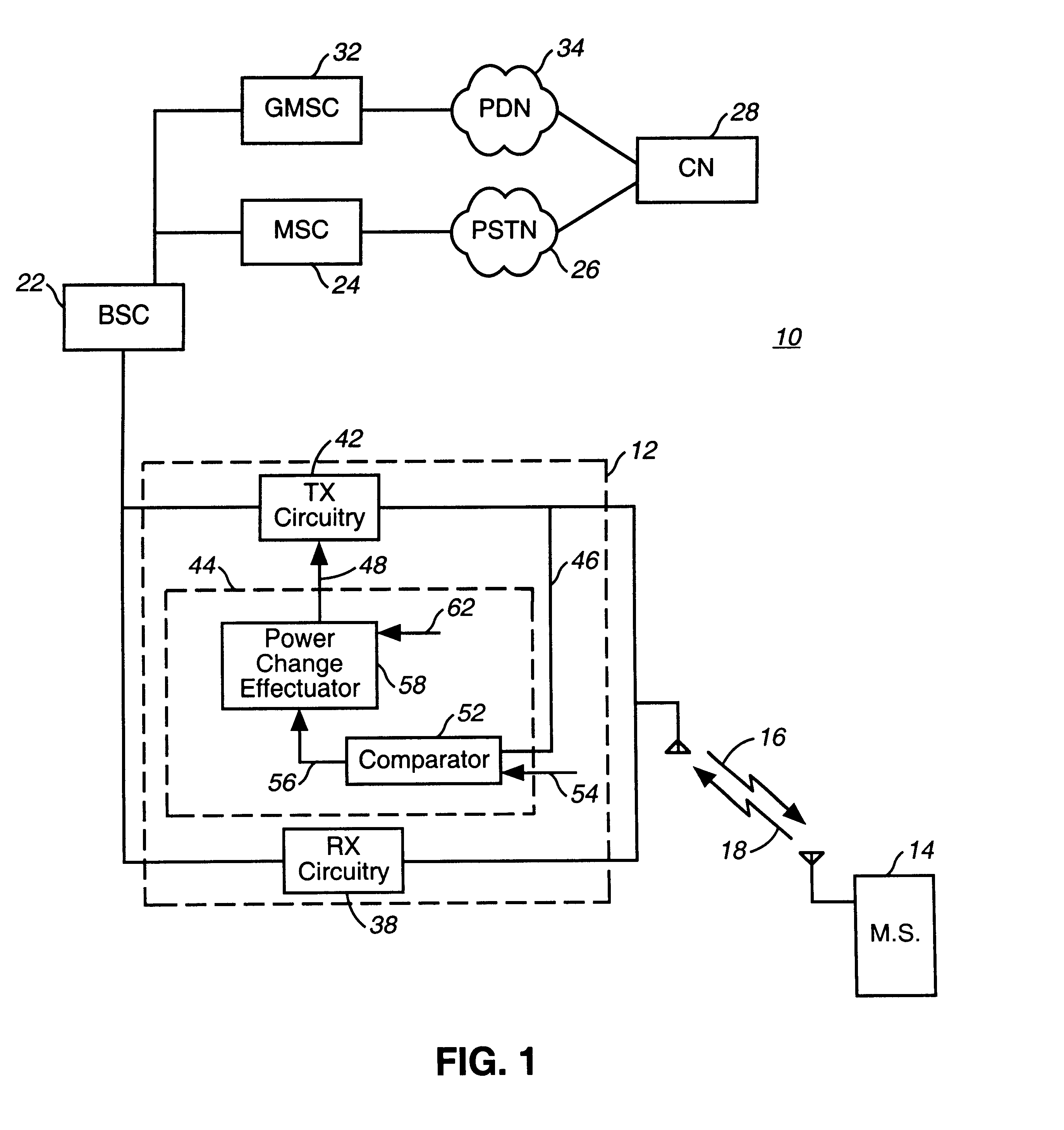
Referring first to FIG. 1, a communication system, shown generally at 10, provides for radio communications between two communication stations, here a base transceiver station (BTS) 12 and a mobile station 14. Radio links are formed between the base station and the mobile station, and communication channels are defined thereupon. Communication signals are communicated between the base station and mobile station upon the communication channels.

In the exemplary implementation shown in the figure, the communication system 10 forms a cellular communication system operable generally pursuant to a GSM (global system for mobile communications) specification which provides for EDGE (enhanced data rates for GSM evolution) communications. It should be understood at the outset, however, that operation of an embodiment of the present invention is similarly also possible in other types of radio, and other, communication systems by which to effectuate power control. Therefore, while the following...


PUM


Abstract

Apparatus, and an associated method, for controlling the power levels at which an EDGE-modulated signal, or other signal which includes envelope varying-portions, during operation of a communication system. Changes in the power levels of the EDGE-modulated signal are permitted when closed-loop power control is done on nonamplitude-modulated component portions of the signal. Changes in the power levels of the EDGE-modulated signal are prevented by open-loop power control on amplitude-modulated component portion of the signal.

Description

The present invention relates generally to a manner by which to effectuate power control over transmit signals generated at a sending station, such as a base transceiver station of a cellular communication system. More particularly, the present invention relates to power-control apparatus, and an associated method, by which to control the power levels of an EDGE (enhanced data rate for GSM evolution)-modulated signal, or other signal which includes an amplitude-modulated component portion. Changes in power levels of the transmit signal are permitted when closed-loop power control is done on non-amplitude-modulated component portions of the signal. And, changes in power level of the transmit signal are prevented by open-loop power control on amplitude-modulated component portions of the signal.BACKGROUND OF THE INVENTIONA communication system is formed, at a minimum, of a sending station and a receiving station. The sending and receiving stations are interconnected by way of a commun...

Claims


Application Information

Patent Timeline
IPC IPC(8): H04B7/005
CPCH04W52/228H04W52/36
Inventor KAIKATI, MUHAMMADSAUKKO, KARI
Owner NOKIA CORP
Learn More