
Fence panel device and modular fence system

a technology of fence panels and components, applied in the field of fence panels and fence assembly systems, can solve the problems of difficult construction of metal fences, inability to easily customize, and affecting the appearance and structural integrity of fences, so as to save time and money, and facilitate installation

Inactive Publication Date: 2005-04-12
CALVERLEY ANTHONY R
View PDF17 Cites 32 Cited by
  • Summary
  • Abstract
  • Description
  • Claims
  • Application Information

AI Technical Summary

Benefits of technology

"The present invention provides a fence system that is easy to install, adaptable to multiple design options, and cost-effective. The fence system can be installed by a person without experience in fence installation. The panels are interlocking and can be customized for shadow box or privacy designs. The fence system is secure and can prevent theft of fence sections or components. The invention also includes methods for making and installing the fence panels. The technical effects of the invention include providing a flexible and cost-effective method for manufacturing corrugated fence panels, providing a fence system that is adaptable to multiple linear designs and curved designs, providing a secure and aesthetically pleasing fence system, and providing a fence system that can be installed by a person without experience in fence installation."

Problems solved by technology

However, weather conditions affect the appearance and structural integrity of wood fences over time.
Fences constructed from alternative materials, such as aluminum and plastic based material, are resistant to inclement weather, last longer and easily maintained, but are not available in shadow box or other panel-like designs and can not be easily customized.
The metal fences known can be difficult to construct, offer little options in design, such as shadow box, privacy designs and curved designs, and are relatively expensive.
In addition, they fail to adequately address security issues, such as theft of fence components or sections.
Various fence designs are known in the art, but none of these addresses or solves the above-noted problems associated with metal fence designs and construction.

Method used


Image

  • Fence panel device and modular fence system
  • Fence panel device and modular fence system
  • Fence panel device and modular fence system

Examples


Embodiment Construction

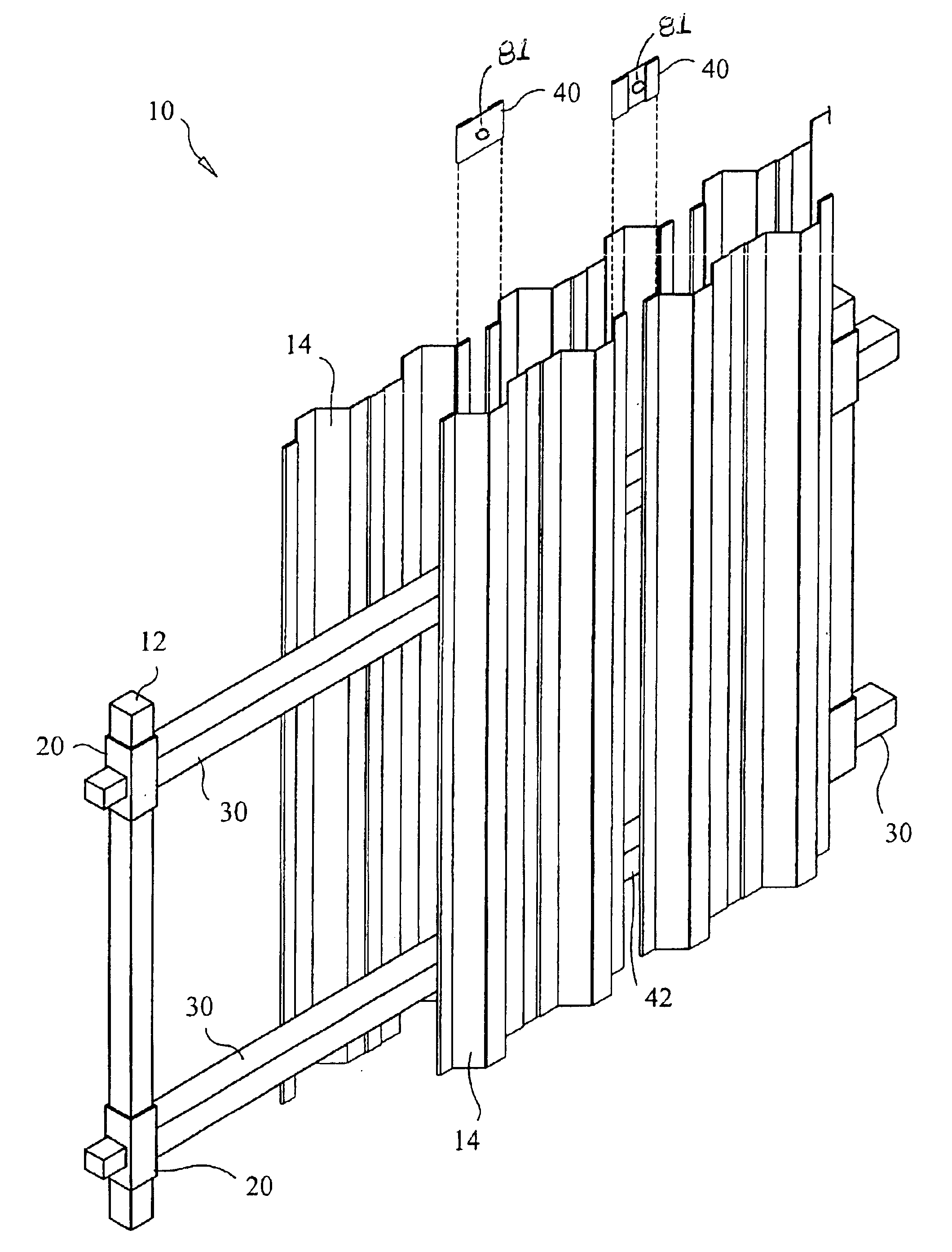
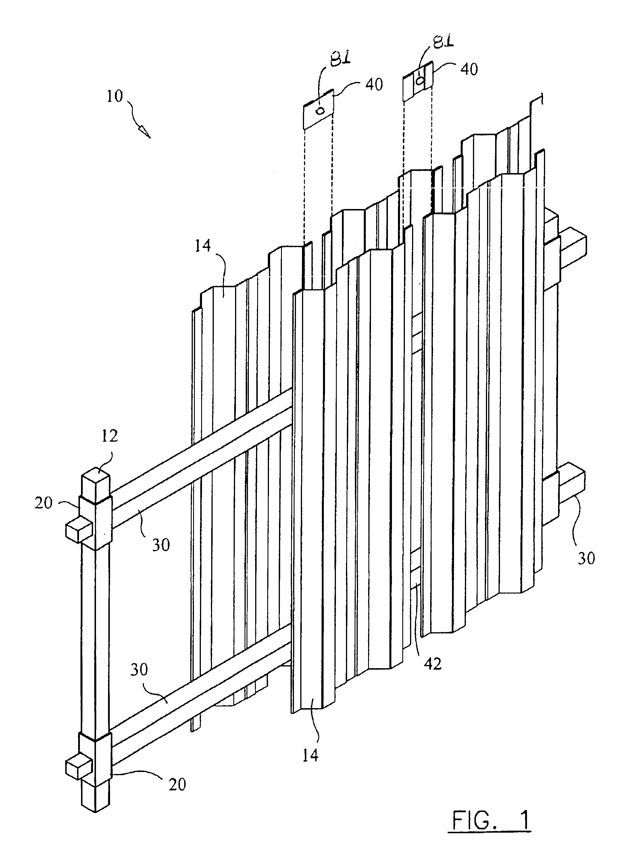
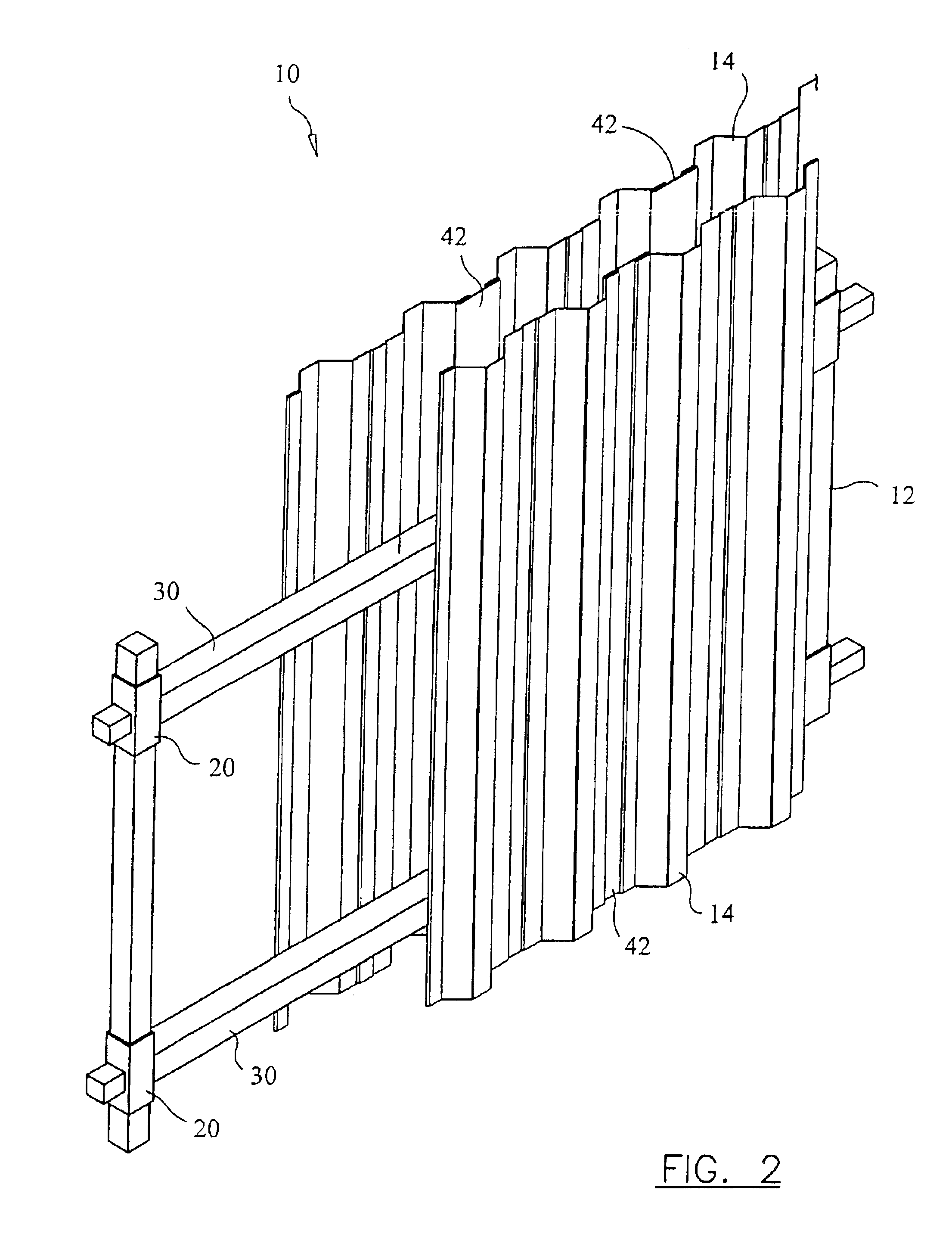
With reference to the drawings, FIGS. 1-22 depict the preferred and alternative embodiments of the instant invention, which is generally characterized by numeric character 10 and / or as a fence or fence system. Referring to FIG. 1, the Fence System 10 preferably comprises a plurality of Posts 12, Panels 14, Post Mounts 20 and Channel Mounts 30. The Fence System 10 is designed to provide an economical, functional, easy to install and customizable fence, such as shadow box, curved or privacy designs. The Posts 12 are preferably rigid and square or rectangular in cross section to provide a flat outside securing surface for structural integrity and can comprise lengths that confirm with recognized standards in the industry, such as eight feet, or lengths that comport with local building codes. The Posts 12 are securable in a ground or ground like surface, such as with cement or dirt, and can comprise a substantially non-corrosive, waterproof and durable material. The preferred material f...


PUM


Abstract

A fencing system and method of manufacturing and installing a fencing system specifically designed to give the appearance of a traditional shadow box or privacy fence, wherein the system uses preformed non-corrosive, structurally sound corrugated panels, posts, posts mounts, channel mounts, and clips that mate and are securable using conventional fasteners.

Description

STATEMENT REGARDING FEDERALLY SPONSORED RESEARCH OR DEVELOPMENTN / ACOPYRIGHT NOTICEA portion of the disclosure of this patent document contains material that is subject to copyright protection. The copyright owner has no objection to the facsimile reproduction by anyone of the patent document or patent disclosure as it appears in the Patent and Trademark Office patent file or records, but otherwise reserves all copyrights rights whatsoever.BACKGROUND OF THE INVENTION1. Field of the InventionThe present invention relates generally to a fence panel and a fence assembly system, and more particularly, to a contoured rust-proof fence panel of symmetrical proportions, fence assembly system having mechanically cooperating parts that incorporate the panels, facilitate convenient fence installation and include linear and curvature designs, and method for making fence panels.2. Description of the Background ArtWood fences and shadow box designs for wood fences are known in the art. However, we...

Claims


Application Information

Patent Timeline
Patent Type & Authority Patents(United States)
IPC IPC(8): E01F8/00E04H17/14
CPCE01F8/0017E01F8/0035E04H17/1434E04H17/1421E04H2017/1473E04H2017/1452E04H17/143E04H17/1447E04H17/1473E04H17/1452E04H17/1417
Inventor CALVERLEY, ANTHONY R.
Owner CALVERLEY ANTHONY R
Learn More