
Wind turbine comprising a planetary gear

a technology of wind turbines and planetary holders, applied in the direction of toothed gearings, mechanical energy handling, liquid fuel engine components, etc., can solve the problems of planetary holders being forced to rotate, wind turbines generating a very strong power, and the rotor being subject to a large risk, etc., to achieve the effect of strong power

Inactive Publication Date: 2005-03-29
HANSEN TRANSMISSIONS INT NV
View PDF3 Cites 73 Cited by
  • Summary
  • Abstract
  • Description
  • Claims
  • Application Information

AI Technical Summary

Benefits of technology

The object of the invention is to provide a wind turbine of the above type which is suited for wind turbines generating a very strong power and which is very compact while ensuring that the bearing of the planetary holder possesses a predetermined resilience.
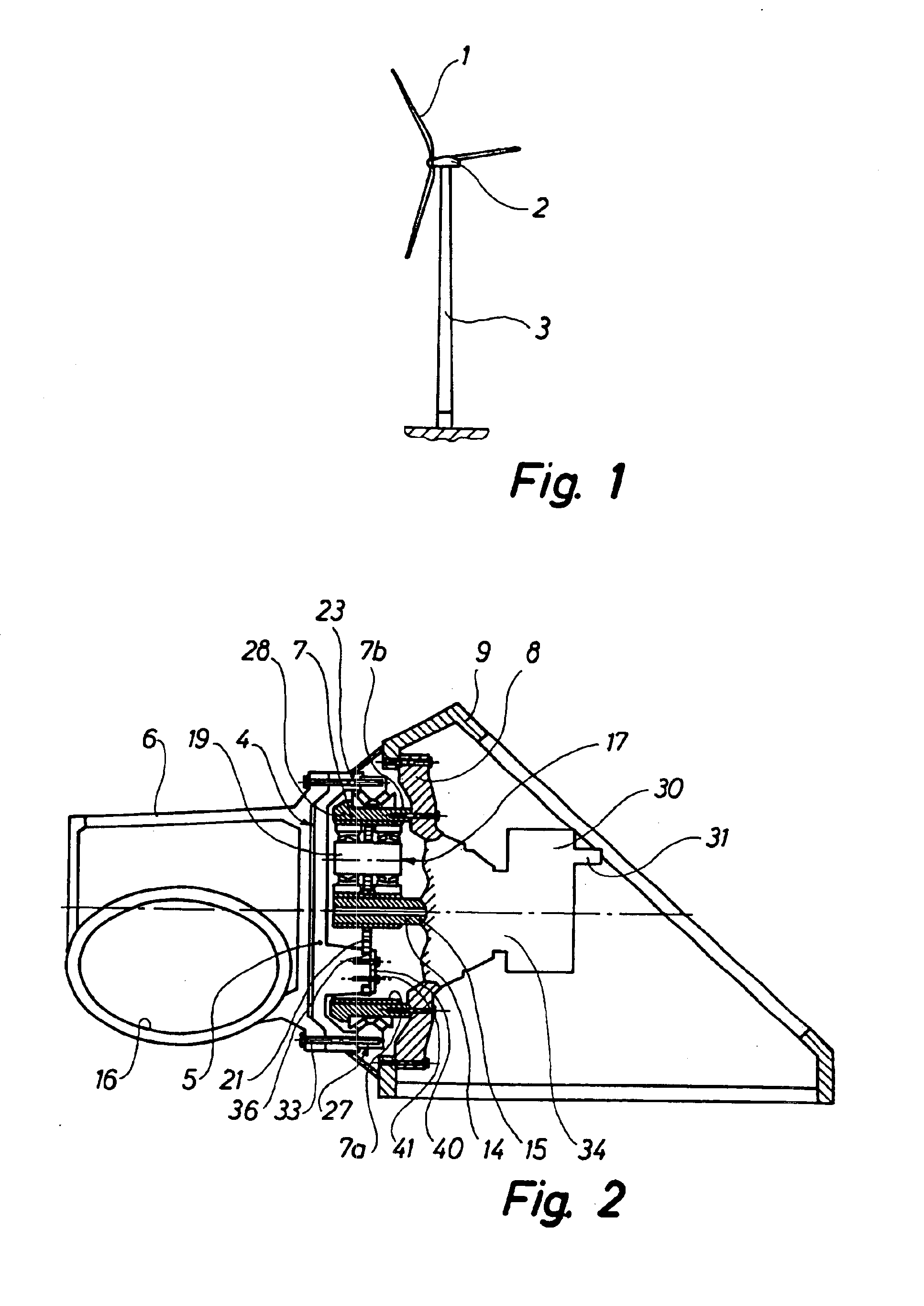
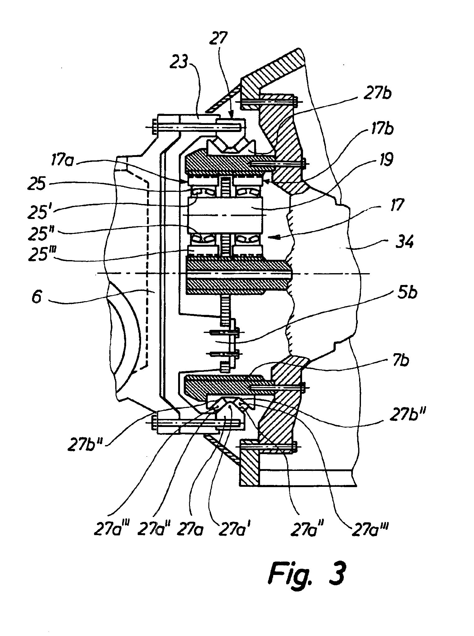
The wind turbine according to the invention is characterised in that the planetary holder is rotatably mounted on the ring gear by means of at least two sets of planetary twin wheels, whereby each set of planetary twin wheels is rotatably mounted on a bogie shaft on the planetary holder, and that said planetary holder is rotatably arranged on the curved outer side of the ring gear by means of an outer radial-axial-roller bearing and through an axially rearwardly directed collar projecting radially beyond said ring gear. As a result, a very compact structure is obtained, and the planetary holder can yield slightly at each planetary wheel of each set of planetary wheels in case it is subjected to heavy stresses on the rotor, said rotor being mounted on said planetary holder.
Moreover, an auxiliary planetary gear may according to the invention be provided behind the planetary gear and built therein for increasing the ratio of the number of revolutions of the electric generator to the number of revolutions of the rotor hub. As mentioned, it is thus possible to increase this ratio.
According to the invention, the outer race in the outer radial-axial-roller bearing of the planetary holder may be provided with a radially inward, circumferential projection with two frustoconical surfaces facing partially away from one another and forming the outer tracks for the rollers of the bearing, whereas an inner race in said bearing may be provided with a corresponding circumferential depression with two frustoconical surfaces partially facing one another and also forming tracks for the bearing rollers. In this manner the radial-axial-roller bearing operates in a particularly reliable manner.
Furthermore according to the invention, the planetary holder may be substantially pot-shaped and be provided with at least two inner axially directed projections, the carrier plate being secured to said projections for instance by being squeezed in a track in said projection by means of an end plate screwed onto said projection. In this manner the carrier plate is secured in a particularly efficient and simple manner.

Problems solved by technology

As the planetary wheels are of a simple and wide structure, and as the bearings are rather rigid, a considerable risk applies of the rotor breaking down in case the forces on the planetary holder are instantaneously very heavy.
Such a structure is not completely satisfactory with respect to wind turbines generating a very strong power.

Method used


Image

  • Wind turbine comprising a planetary gear
  • Wind turbine comprising a planetary gear
  • Wind turbine comprising a planetary gear

Examples


Embodiment Construction

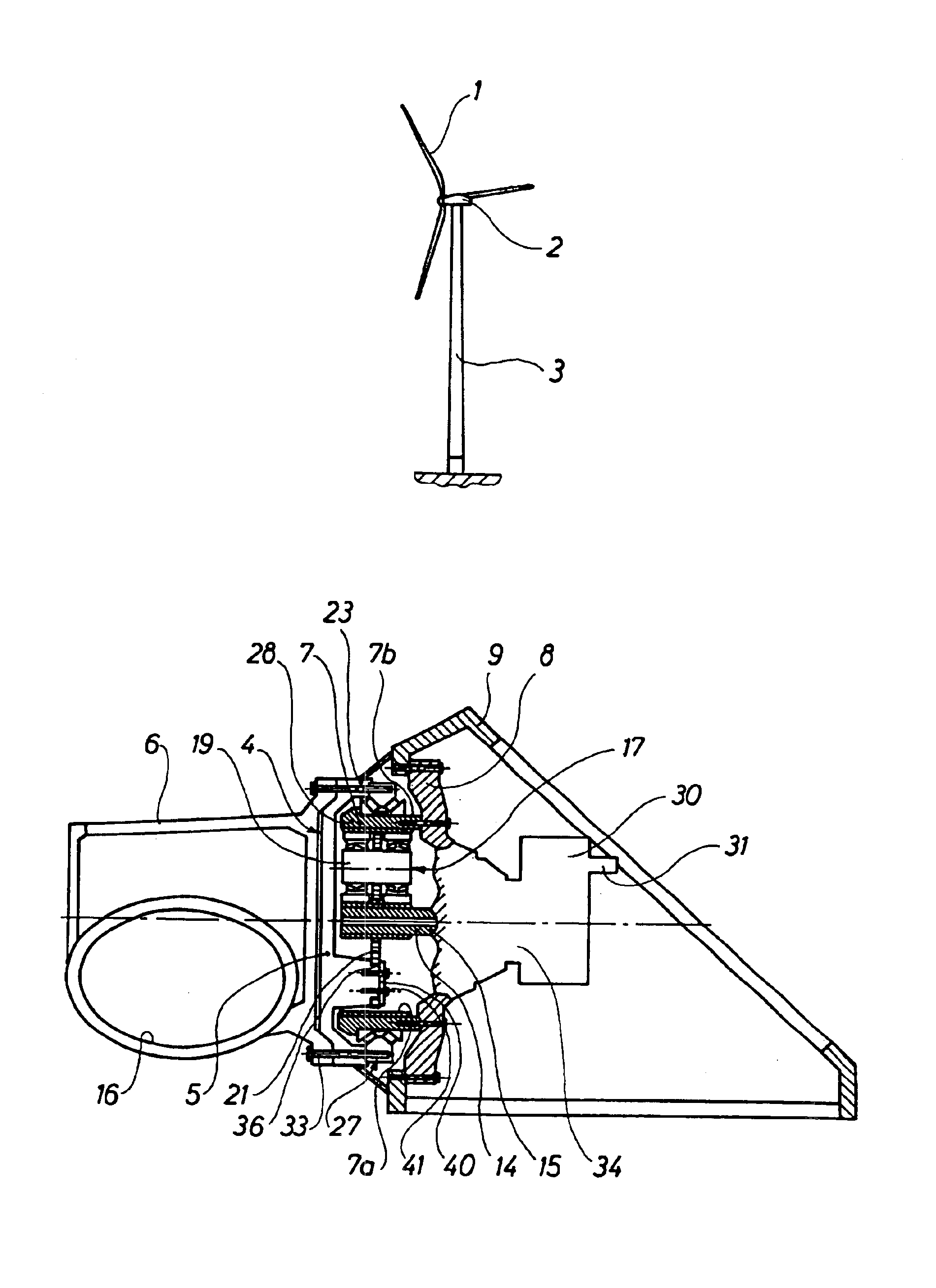
The wind turbine shown in FIG. 1 comprises a rotor 1, a nacelle 2 and a tower 3. As illustrated in FIGS. 2 and 3, the nacelle 2 comprises a planetary gear 4, and the hub 6 of the rotor 1 is rigidly secured to the planetary holder 5 of said planetary gear 4. The planetary gear 4 is connected or connectable to the shaft of an electric generator not shown. The planetary gear 4 comprises a ring gear 7 provided with a toothing 7a on the side turning radially inwards. The ring gear 7 is fixedly mounted on a housing part 8, which in turn is rigidly connected to an engine frame 9 in the nacelle. The ring gear 7 can optionally be secured directly to the engine frame 9. The planetary gear 4 comprises planetary wheels 17 engaging a centrally arranged sun wheel 14 which comprises a tubular extension 15. A parallel gear 30 can be inserted between the tubular extension and the generator shaft not shown, said parallel gear being diagrammatically indicated. The output shaft of the parallel gear is ...


PUM


Abstract

A wind turbine with a rotor, a nacelle and a tower. The nacelle comprises a planetary gear (4) with a planetary holder (5), on which the hub (6) of the rotor is rigidly secured, and which can be connected to the shaft of an electric generator. The planetary gear (4) comprises a ring gear (7) fixedly mounted on an engine frame (9) in the nacelle or on the member (8) rigidly connected to said frame. The planetary wheels (17a, 17b) of the planetary gear can run around a centrally arranged sun wheel (14) while engaging the latter. The sun wheel is optionally connected to a parallel gear (30). The planetary holder (5) is rotatably mounted in the ring gear (7) by means of at least two sets (17) of planetary twin wheels (17a, 17b). Each set of planetary twin wheels is mounted on a bogie shaft (19) on the planetary holder. Through an axially rearward collar (23) projecting beyond the ring gear, the planetary holder (5) is also rotatably arranged on the curved outer side (7b) of the ring gear (7) by means of an outer radial-axial-roller bearing (27). As a result, a wind turbine is obtained which is suited for generating very strong power and which is very compact and ensures a very advantageous transfer of the power at each planetary wheel.

Description

TECHNICAL FIELDThe invention relates to a wind turbine with a rotor, a nacelle and a tower, and where the nacelle comprises a planetary gear with a planetary holder on which the hub of the rotor is rigidly connected, said planetary holder being connected or connectable to the shaft of an electric generator, and where the planetary gear comprises a ring gear fixedly mounted on an engine frame in the nacelle or on a member rigidly connected to said frame, and where the planetary wheels of the planetary gear can run around a centrally arranged sun wheel, said planetary wheels engaging said sun wheel which is optionally connected to a parallel gear.BACKGROUND ARTSuch a wind turbine with a rotor, a nacelle and a tower is known, where the hub of the rotor is rigidly secured to the planetary holder of a planetary gear and not to a main shaft which is the conventional mounting. A ring gear for the planetary gear is fixedly mounted inside a tubular member of the known wind turbine, said tubu...

Claims


Application Information

Patent Timeline
Patent Type & Authority Patents(United States)
IPC IPC(8): F16H1/28F03D1/00F03D1/06F03D80/70H02K7/116
CPCF03D1/00F03D11/0008F16H1/2827F16H1/2836F05B2260/40311Y10S415/908Y02E10/722Y02E10/725Y02E10/726F16H2001/289Y02E10/721F03D80/70Y02E10/72
Inventor CHRISTENSEN, MOGENS
Owner HANSEN TRANSMISSIONS INT NV
Learn More