
Beverage closure with open/close spout and protected seal surfaces

Active Publication Date: 2005-03-29
BERRY PLASTICS CORP
View PDF41 Cites 16 Cited by
  • Summary
  • Abstract
  • Description
  • Claims
  • Application Information

AI Technical Summary

Benefits of technology

The present application is related to closures for beverage containers; and more specifically, to a closure having an open / close type spout and plug, where the sealing surfaces within the closure are reduced and / or are protected from damage, thereby improving the performance and consistency of the closure product. This application is relevant to both push / pull type spouts and to twist open / close spouts.
Accordingly, it is a first aspect of the invention to provide a closure for a beverage container that includes: (a) a base adapted to be attached to an opening of a liquid container, where the base includes a conduit extending therethrough that is adapted to be in fluid communication with liquid contents of the liquid container, where the base further includes a substantially tubular spout guide defining at least a portion of the conduit, and where the base further includes an annular deck extending radially inwardly from an inner circumferential surface of the base defining a central orifice in fluid communication with the conduit; and (b) a substantially annular spout mounted to the tubular spout guide for reciprocation at least between an open position and a closed position, the spout including (1) an annular wall and (2) a plug positioned radially within the annular wall; where the plug has annular, outer circumferential seal surface that is received within, and plugs the central orifice of the deck when the spout is in the closed position and that is removed from the central orifice deck when the spout is in the open position; where at least a substantial portion of the outer circumferential seal surface of the plug is axially recessed or flush with respect to the annular wall of the spout; and where the outer circumferential seal surface has either a smooth cylindrical shape with a substantially constant diameter or a smooth frustoconical shape having a diameter that widens with the distance from the leading end. The annular wall of the spout protects the substantial portion of the seal surface from damage during the molding and assembly operations; and, further, the shape of the plug and corresponding mold makes the plug less susceptible to damage when the spout is axially ejected from a mold after a molding operation.
It is a second aspect of the invention to provide a closure for a container adapted to contain a liquid that includes: a base adapted to be attached to an opening of a liquid container, where the base includes a conduit extending therethrough that is adapted to be in fluid communication with liquid contents of the liquid container when attached to the opening of the liquid container, and where the base further includes a substantially tubular spout guide defining at least a portion of the conduit and a plug positioned radially within the tubular spout guide; and a substantially annular spout mounted to the tubular spout guide for reciprocation at least between an open position and a closed position, where the spout includes an annular wall and an annular deck extending radially inwardly from an upper end of the annular wall forming a central orifice; where the plug has an annular, outer circumferential seal surface that is received within, and plugs the central orifice of the deck when the spout is in the closed position and that is removed from the central orifice deck when the spout is in the open position; and where at least a substantial portion of the outer circumferential seal surface of the plug is axially recessed or flush with respect to the tubular spout guide such that the tubular spout guide protects the substantial portion of the seal surface from damage during the molding and assembly operations.
In yet another alternate detailed embodiment of the second aspect of the invention, the deck includes an annular lip extending axially downward from the central orifice providing additional inner circumferential surface area for sealing about the plug when the spout is in the closed position. In a further detailed embodiment, the deck is flexible and substantially resilient.
In a more detailed embodiment of the third aspect of the invention, at least a substantial portion of the outer circumferential seal surface of the plug is axially recessed or flush with respect to the annular wall of the spout such that the annular wall of the spout protects the substantial portion of the seal surface from damage during the molding and assembly operations. In a further detailed embodiment, the outer circumferential seal surface has a shape that is: (i) a smooth cylindrical shape having a substantially constant diameter, or (ii) a smooth frustoconical shape having a diameter that widens with the distance from the leading end, such that the plug is less susceptible to damage when the spout is axially ejected from a mold after a molding operation.

Problems solved by technology

Thus, during the molding process, the plug's sealing surface (which will seal against the corresponding sealing surface of the orifice) can be scratched or damaged due to impacting the mold components while being stripped off or ejected from the cores of the mold.
The sealing surface is also subject to slight damage during the sorting and handling that occurs during the automatic assembly process of the closure, as well as the manipulation that occurs during filling and final assembly of the closure to the container.
The scratching and damage that occurs can create a seal failure which is more severe when trying to hold a positive or negative pressure in the container.
Both designs have had limited tamper evident success because the only way the consumer can determine whether the closure has been previously opened is by the feel of the bridges breaking or the sound of the bridges breaking.
When the overcap is re-applied after the initial opening, it is difficult to see if the closure has been opened since the overcap is in the same position in relation to the portion that was broken prior to opening.

Method used


Image

  • Beverage closure with open/close spout and protected seal surfaces
  • Beverage closure with open/close spout and protected seal surfaces
  • Beverage closure with open/close spout and protected seal surfaces

Examples


Embodiment Construction

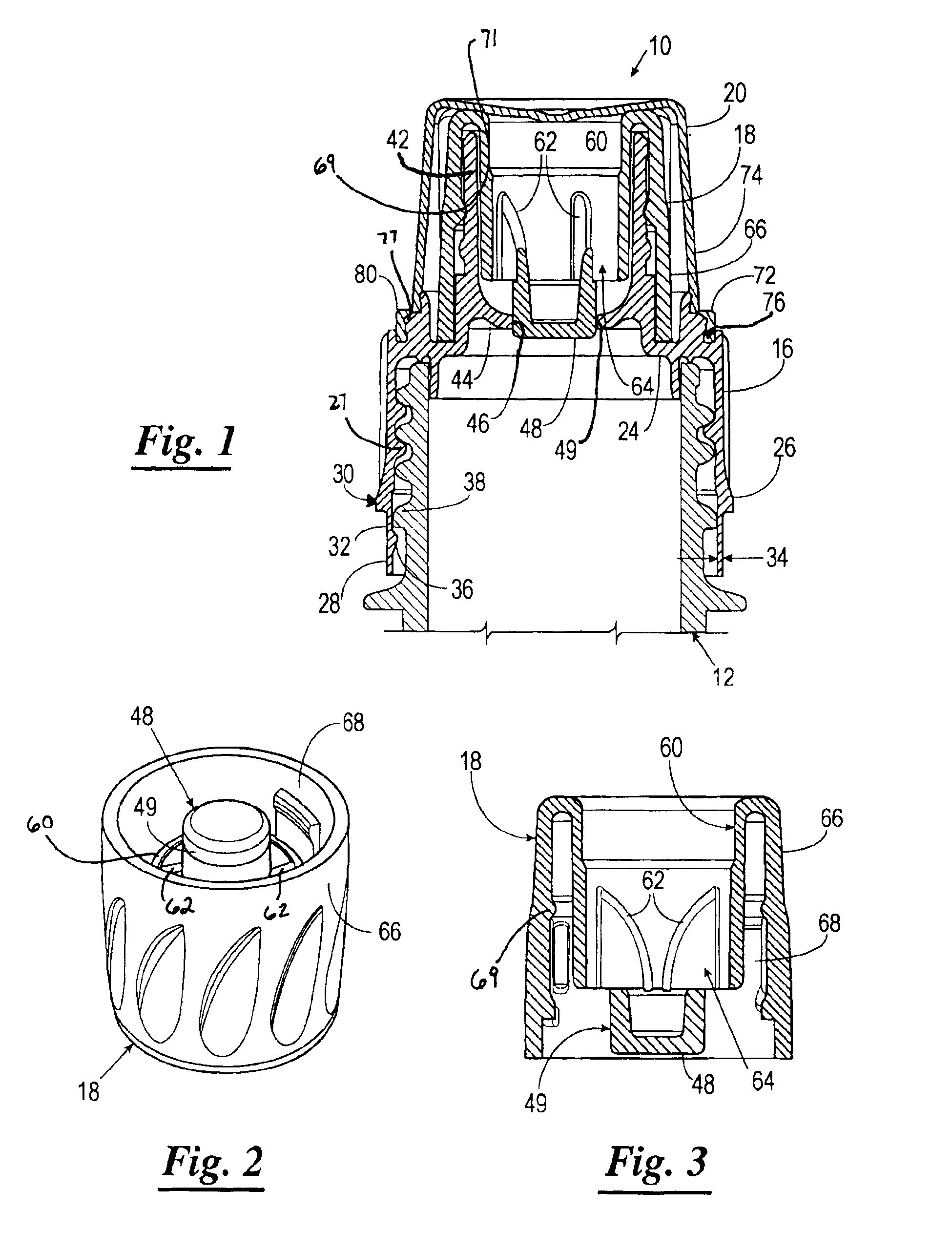
Referring now to the drawings, and in particular to FIGS. 1-3, shown therein is an exemplary embodiment of a closure 10 for a container 12, such as a bottle. The closure 10 includes a base 16, a spout 18, and an overcap 20. The base 16 is adapted to be threaded onto the container 12. The base 16 includes a generally cylindrical sidewall 26 including an internal helical thread 27 for threading the base 16 onto a throat of the container 12, an annular top wall 24 extending radially inward from the upper end portion of the sidewall, and an annular tamper band 28 extending from a lower end 30 of the sidewall 26. The tamper band 28 is attached to the side wall 26 with a plurality of bridges 32 formed by a cutting process subsequent to the molding process. The tamper band 28 has a thickness 34 which is less than that of the sidewall 26 of the base 16. The reduced thickness functions to provide the tamper band 28 with a certain degree of flexibility to facilitate application of the closure...


PUM


Abstract

A closure includes: (a) a base attached to an opening of a container, a conduit extending therethrough in fluid communication with contents of the container, a tubular spout guide defining a portion of the conduit, an annular deck extending radially inwardly from an inner circumferential surface of the base defining a central orifice in fluid communication with the conduit,;and (b) an annular spout mounted to the tubular spout guide for reciprocation between an open position and a closed position, the spout including (1) an annular wall and (2) a plug positioned radially within the annular wall; the plug has annular, outer circumferential seal surface that is received within, and plugs the central orifice of the deck; a portion of the seal surface of the plug is axially recessed or flush with the annular wall of the spout; the seal surface has either a cylindrical shape or a frustoconical shape.

Description

BACKGROUNDThe present application is related to closures for beverage containers; and more specifically, to a closure having an open / close type spout and plug, where the sealing surfaces within the closure are reduced and / or are protected from damage, thereby improving the performance and consistency of the closure product. This application is relevant to both push / pull type spouts and to twist open / close spouts.Prior art closures having an open / close type spout and plug typically include at least two components: a base component that attaches to the throat of a beverage container, and a spout component that is carried on the base component and is adapted to be reciprocated between and open and close position with respect to the base component by a consumer. Typically, the base component includes an opening coaxial with the throat of the beverage container and a coaxial plug extending from the opening, and the spout component includes a coaxial orifice that is in fluid communication...

Claims


Application Information

Patent Timeline
IPC IPC(8): B65D47/04B65D47/24B65D41/34B65D51/18
CPCB65D41/3447B65D47/242B65D51/18B65D47/243B65D2101/0038B65D2401/25
Inventor STONEBERG, THOMAS C.KUBITZ, TERRY E.TORTORELLA, DENNIS J.
Owner BERRY PLASTICS CORP
Learn More