
Bottle having reserve reservoir

a technology of bottle and reservoir, applied in the field of bottles and bottles, can solve the problems of low efficiency and achieve the effect of increasing the efficiency of dispensing

Inactive Publication Date: 2005-03-29
SNIDER ROBERT J
View PDF4 Cites 20 Cited by
  • Summary
  • Abstract
  • Description
  • Claims
  • Application Information

AI Technical Summary

Benefits of technology

Yet another object of the present invention is to provide a novel fluid dispensing bottle having a pair of fluid reservoirs or compartments which will allow the user to dispense a total amount of fluid normally carried in the container and to dispense the fluid through the very last drop.
Yet a further object is to provide a bottle having a secondary fluid reservoir for increasing the dispensing efficiency so as to encourage people to buy refills and to reuse the bottle, thus benefiting the environment.

Problems solved by technology

Although such a bottle is successful for containing a large amount of fluid and for dispensing this fluid through the nozzle, problems and difficulties have been encountered which stem largely from the fact that the tube or hose seldom is effective in withdrawing the last portion of the fluid which is adjacent to the bottom of the bottle.

Method used


Image

  • Bottle having reserve reservoir
  • Bottle having reserve reservoir

Examples


Embodiment Construction

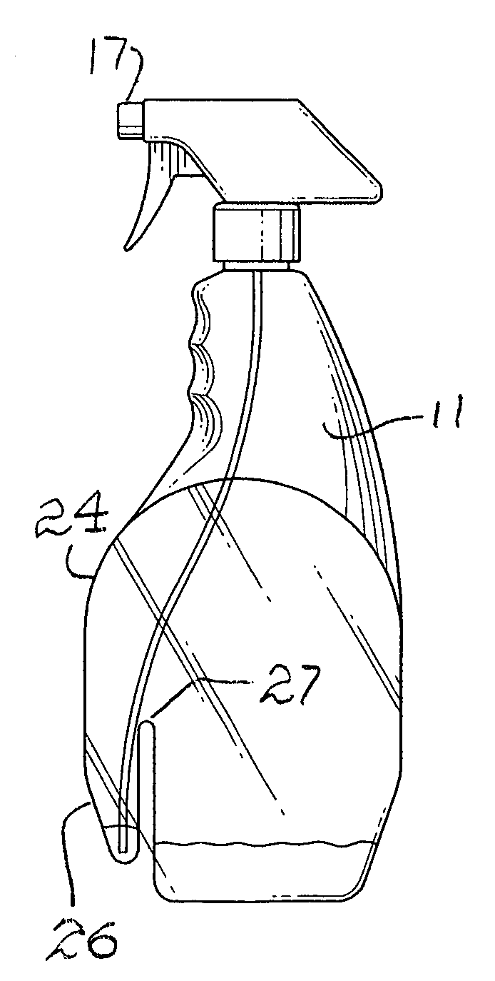
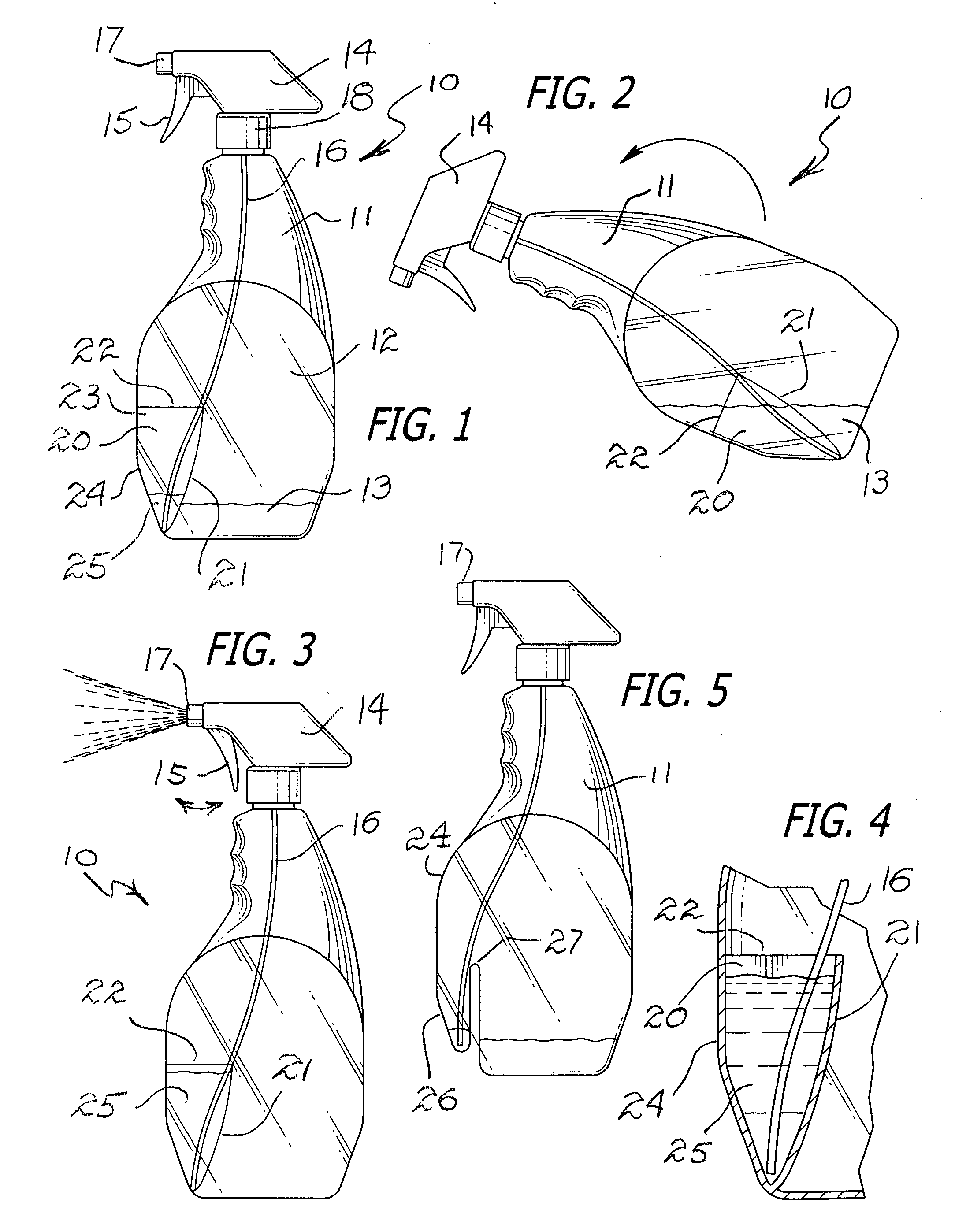
Referring to FIG. 1, a container, such as a bottle, having a secondary or reserve reservoir is indicated in the direction of arrow 10, which includes a bottle 11 with a primary sidewall 24 enclosing a major storage internal area, illustrated by numeral 12, into which a bulk quantity of fluid 13 is carried. The fluid 13 is intended to be withdrawn or removed from the major storage area by means of a manual pump, having a body 14 with a trigger 15, for reciprocal operation of a plunger causing the fluid 13 to be drawn through the open end of a hose or tube 16 for dispensing via a nozzle 17. The pumping means can be removably affixed to the top of the bottle 11 by means of a threaded collar 18 with a threaded bottle neck.

FIG. 1 also illustrates that the interior of the bottle includes a secondary or reserve reservoir indicated by numeral 20, which includes a secondary sidewall 21 having an opening at its top, forming a lip, as indicated by numeral 22. The opening is defined by an edge...


PUM


Abstract

A container having an internal storage area for holding a quantity of fluid. The top of the bottle is provided with a manual trigger-type pump and includes a downwardly depending tube for conducting or syphoning the fluid from the storage area. The internal storage compartment further includes a reserve reservoir for holding a secondary portion of fluid into which the open end of the tube is disposed after the storage area has been substantially emptied through normal operation of the pump. A small remaining portion of the stored fluid is distributed into the reservoir and the open end of the tube is placed therein so that the last portion of fluid can be dispensed in the normal way by the pump. The secondary or reserve reservoir is defined by a curved inner wall, having opposite ends integrally formed with the sidewall of the bottle. The sidewall is open at its top and tapers gently towards the bottom of the bottle. The edge marginal region of the wall, defining the opening leading into the interior of the secondary or reserve reservoir, constitutes a lip over which the last remaining portion of the fluid will flow when the bottle is tipped forward.

Description

BACKGROUND OF THE INVENTION 1. Field of the Invention The present invention relates to the field of dispensers, storage containers and bottles, and more particularly to a novel bottle having a primary storage area into which fluid is held, and which further includes a reserve reservoir defined by an inner wall serving as a secondary fluid reservoir into which a syphoning or dispensing apparatus is immersed wherein the last remaining portion of the fluid supply can be withdrawn from the bottle. 2. Brief Description of the Prior Art In the past, it has been the conventional practice to provide a fluid container, such as a bottle, with an internal storage area occupied by a selected fluid. The fluid is normally withdrawn from the interior of the bottle by means of a pump or syphoning means, which includes a hose or tube immersed in the fluid so that upon manual squeezing of a trigger mechanism, the fluid is pumped through the hose or tube into a dispensing jet for distribution external...

Claims


Application Information

Patent Timeline
Patent Type & Authority Patents(United States)
IPC IPC(8): B05B11/00B65D1/04
CPCB05B11/0037B05B11/0059B65D1/04B65D2231/005B05B11/3057B05B11/1057
Inventor SNIDER, ROBERT J.
Owner SNIDER ROBERT J
Learn More