
Emulation of dynamically reconfigurable computer system

a computer system and dynamic reconfiguration technology, applied in the field of peripheral device emulation, can solve problems such as limited use of power data line connection

Inactive Publication Date: 2005-03-15
HEWLETT PACKARD DEV CO LP
View PDF12 Cites 18 Cited by
  • Summary
  • Abstract
  • Description
  • Claims
  • Application Information

AI Technical Summary

Benefits of technology

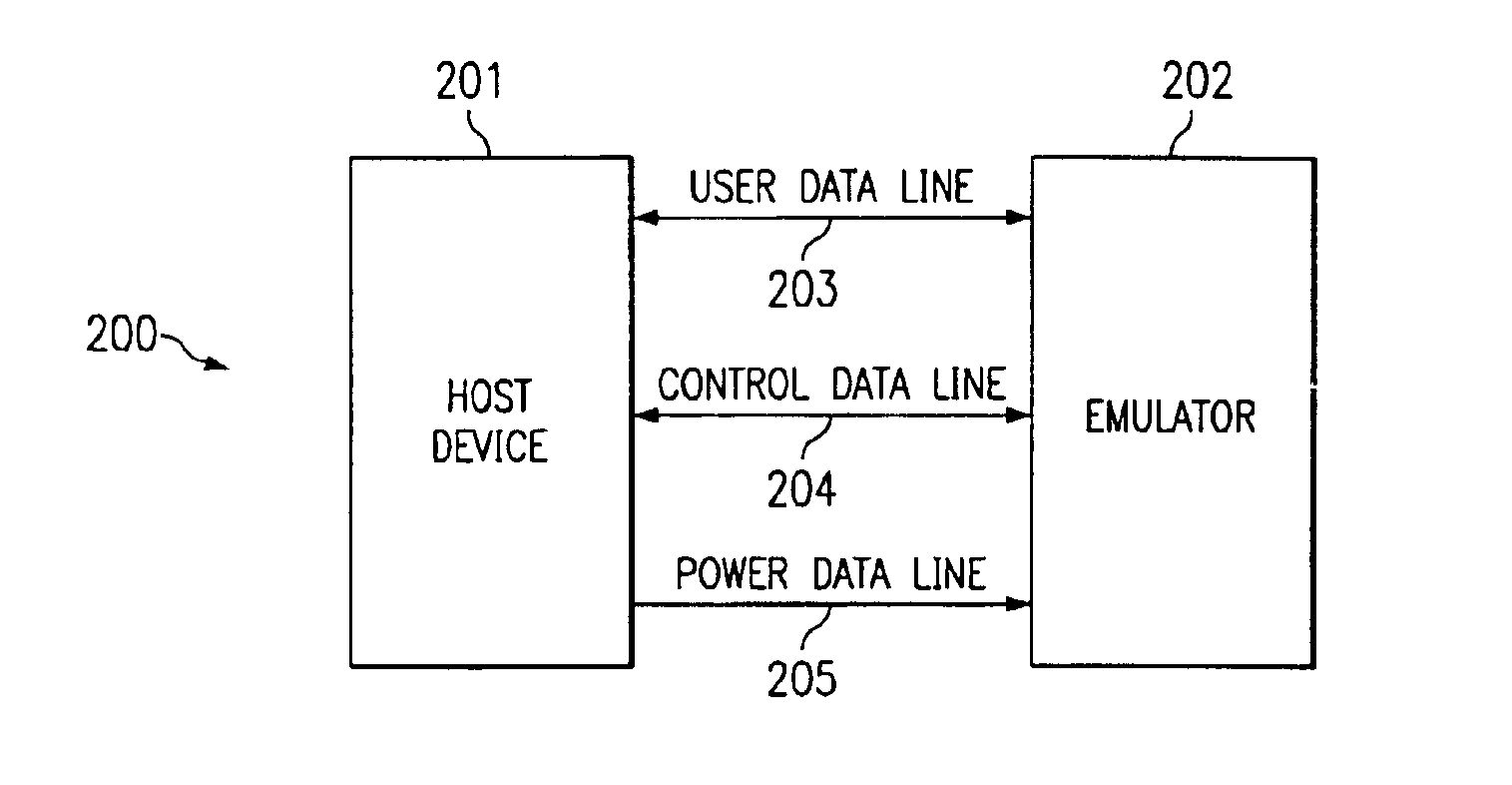
In a preferred embodiment, deployment of a power data line connection between the host computer and a peripheral may be used to detect the physical presence or absence of a peripheral device at a point of connection to a host device. Use of the power data line connection may be limited to such mere presence detection where the peripheral device being emulated is powered separately from the host computer. However, alternatively, the emulator may receive data representing power values along a power data line connection, thereby enabling the host device to both control and monitor a level of emulated power transmission to a device being emulated by the emulator.
Accordingly, it is an advantage of a preferred embodiment of the present invention that the host device is able to monitor and establish the control and power settings for an emulated device employing control and power connection lines of the present invention.
It is a further advantage of a preferred embodiment of the present invention that diagnostic and recovery functionality within the host device may be more fully exercised than in prior art systems.
It is a still further advantage of a preferred embodiment of the present invention that dynamic connection and disconnection of peripheral devices to a host device may be practiced employing information pertaining to transient power characteristics of various peripheral devices.

Problems solved by technology

Use of the power data line connection may be limited to such mere presence detection where the peripheral device being emulated is powered separately from the host computer.

Method used


Image

  • Emulation of dynamically reconfigurable computer system
  • Emulation of dynamically reconfigurable computer system
  • Emulation of dynamically reconfigurable computer system

Examples


Embodiment Construction

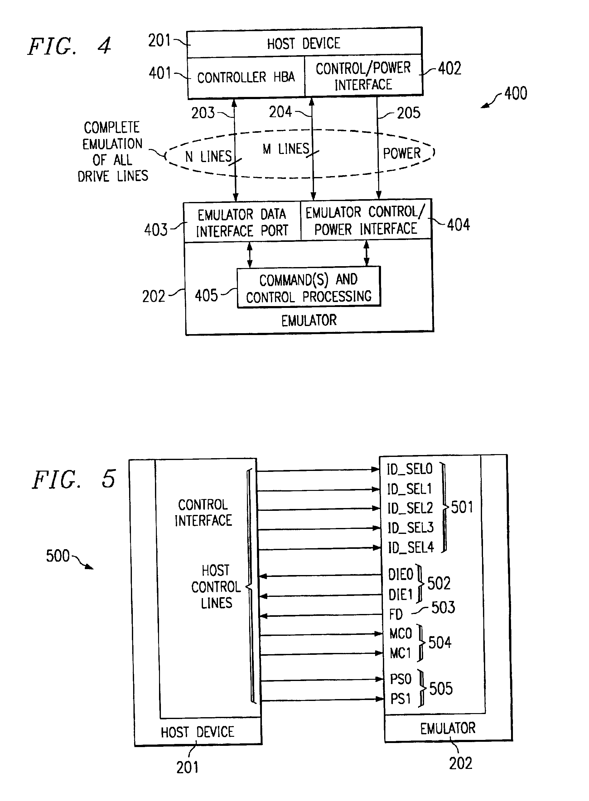
FIG. 2 depicts an apparatus 200 for connecting a host device to an emulator according to a preferred embodiment of the present invention. The embodiment of FIG. 2 preferably operates to enable more accurate emulation of various peripheral devices emulated by emulator202 than was possible employing the systems of the prior art. This more accurate emulation is preferably made possible by more accurately representing the physical interface between the host device 201 and a hypothetical peripheral device by employing a plurality of connection lines between the host device 201 and emulator 202. Although the embodiment of FIG. 2 depicts three such connection lines, it will be appreciated that fewer or more than three such connection lines may be employed, and that all such variations are included within the scope of the present invention. Although the following discussion generally concerns an embodiment in which host device 201 is connected to a single emulator 202, where emulator 202 em...


PUM


Abstract

The present invention relates to a system and method for emulating a greater range of behavior of a peripheral device connected to a host device or host computer than was available in the prior art. The emulation of a greater range of activity of the peripheral device provides an opportunity to more fully test the interaction of a host device with the emulated peripheral device. More specifically, the present invention preferably adds control data line and power data line connections to user data line connections between the host device and an intelligent emulator so that variations in control settings and power levels may be exercised in addition to manipulation of transmissions along a user data line, thereby more fully exercising host device interaction with an emulated device.

Description

TECHNICAL FIELDThe present invention relates in general to peripheral device emulation and in particular to including emulation of control and power circuitry in peripheral device emulation.BACKGROUNDWhen constructing data processing or communication equipment, it is generally desirable to emulate the operation of various components and the interaction of these components with each other before all such components are available for actual physical testing. Such emulation generally enables the identification of potential fault conditions to be identified and the exercise of software within host devices designed to identify and respond to fault conditions originating within peripherals or other devices.Generally, prior art systems are able to emulate data communication between the host and its peripheral devices occurring under steady state conditions. This may be accomplished by connecting data communication wiring or cabling between the host and emulator and causing the host equipme...

Claims


Application Information

Patent Timeline
Patent Type & Authority Patents(United States)
IPC IPC(8): G06F9/455G06F11/26
CPCG06F11/261
Inventor MARGULIEUX, GORDON
Owner HEWLETT PACKARD DEV CO LP
Learn More