
Apparatus and method for high dynamic range imaging using spatially varying exposures

a high-dynamic range, image sensor technology, applied in the direction of color television, television system, color signal processing circuit, etc., can solve the problems of insufficient capture of insufficient dynamic range of known image sensing devices, and inability to capture the fine details of most real-life scenes. , to achieve the effect of substantial loss of image detail

Inactive Publication Date: 2005-03-08
THE TRUSTEES OF COLUMBIA UNIV IN THE CITY OF NEW YORK +1
View PDF8 Cites 176 Cited by
  • Summary
  • Abstract
  • Description
  • Claims
  • Application Information

AI Technical Summary

Benefits of technology

The present invention provides a system for high dynamic range imaging by using an image sensor with a low dynamic range. The image sensor senses the image and provides pixel values representing the light intensities impinging on the light-sensing elements. The image sensor has a saturated pixel value when the intensity of light exceeds a threshold level and a blackened pixel value when the intensity of light is below a threshold level. The system includes a mask with a multiplicity of light-transmitting cells, each controlling the exposure of a respective light-sensing element. The mask has exposure control signals that can be applied to alter the exposure of the light-sensing elements. The system also includes an exposure reapplicator for applying the exposure control signals to a second array of light-sensing elements to create a smooth exposure value for the image. The normalizer maps the pixel values to a standard exposure value based on the response function of the image sensor. The system can capture high dynamic range images with reduced loss of image detail and provides a compressed dynamic range image for viewing on a display with a relatively low dynamic range.

Problems solved by technology

In contrast, known image sensing devices have very limited dynamic ranges.
In the case of grey-scale images, 8-bits provide only 256 discrete grey levels, which is not sufficient to capture the fine details of most real life scenes.
However, techniques that require acquiring multiple images while temporally changing the exposure have the fundamental problem in that variations in the scene may take place between exposure changes.
Finally, because a greater time is needed to sequentially capture all the required images, the temporal exposure variation techniques are not suitable for real time applications.
This technique has the disadvantage of requiring complex and expensive optics, and capturing images with more than two different exposures becomes difficult.
However, the Murakoshi reference does not address the problem of capturing high dynamic range images using a low dynamic range image sensor.
However, the apparatus and method of the Ross et al. reference is aimed at simplifying three-dimensional measurement using projected light, and there is nothing in the reference on how to capture a high dynamic range image.
Another problem of known systems for capturing high dynamic range images is the display of such images using low dynamic range displays.
However, tone curve reproduction compression does not preserve visual details of the scene.
Histogram equalization results in a more even redistribution of the colors in the image over the space of colors, but this technique cannot sufficiently preserve the detail of an image which has several local areas with very bright (or very dark) pixels, where such local areas together may span the complete range of grey levels.
However, this technique has the drawback of requiring large amounts of memory and extensive computations to obtain the frequency component images.

Method used


Image

  • Apparatus and method for high dynamic range imaging using spatially varying exposures
  • Apparatus and method for high dynamic range imaging using spatially varying exposures
  • Apparatus and method for high dynamic range imaging using spatially varying exposures

Examples


Embodiment Construction

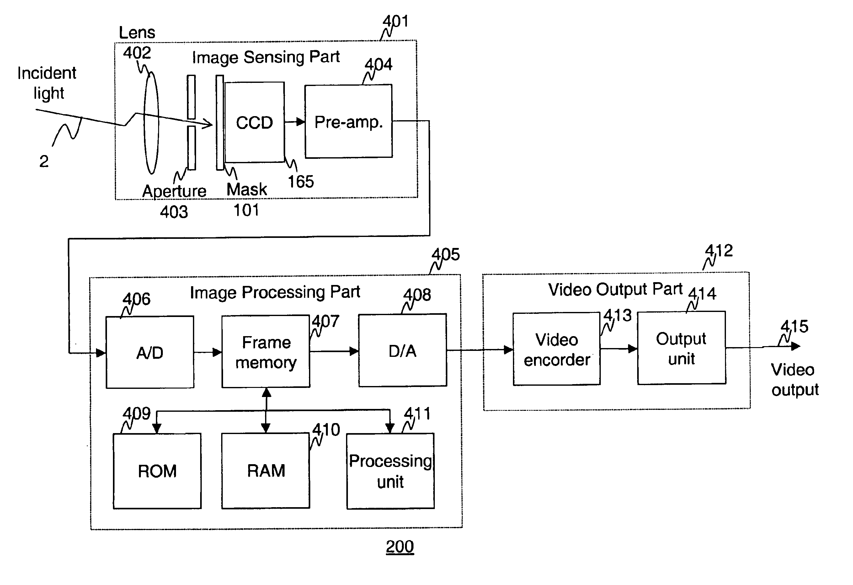
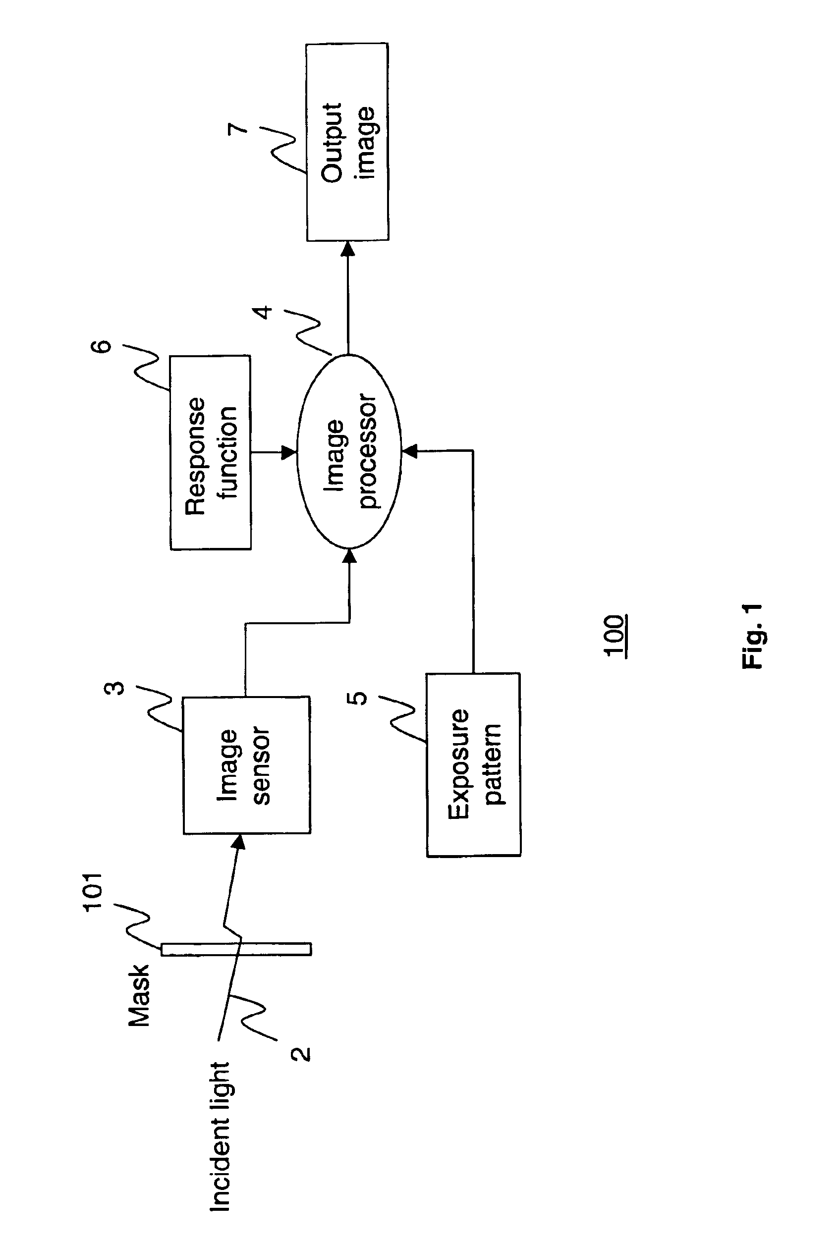
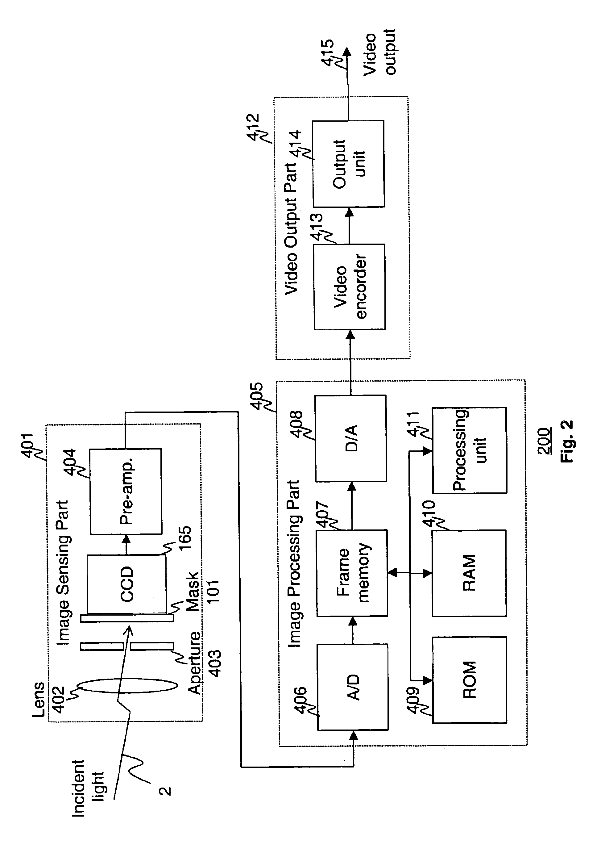
Referring now to FIG. 1, there is shown a functional diagram of an imaging system 100 according to a first exemplary embodiment of the present invention. The system 100 includes a mask 101 through which incident light 2 from a scene (not shown) passes before impinging on an image sensor 3. The image sensor 3 senses an image of the scene as transmitted by the mask 101 and provides corresponding pixel values to an image processor 4, which is coupled to a response function memory 6 and an exposure pattern memory 5 and which provides high dynamic range image data to an output image memory 7. The mask 101 is a plate of transparent material which has neutral characteristics with respect to the wavelengths of the incident light and has a fixed spatial pattern of transparency in the region through which the incident light 2 passes. The term “light” as used in the specification and claims refers to electromagnetic radiation spanning the spectrum from the millimeter wave region to the gamma r...


PUM


Abstract

Apparatus and methods are provided for obtaining high dynamic range images using a low dynamic range image sensor. The image of a scene is captured with an image sensor using a spatially varying exposure function. The spatially varying exposure function can be implemented in a number of ways, such as by using as an optical mask with a fixed spatial attenuation pattern or by using an array of light sensing elements having spatially varying photosensitivities. The captured image is then normalized with respect to the spatially varying exposure function. The normalized image data can be interpolated to account for pixels that are either saturated or blackened to enhance the dynamic range of the image sensor.

Description

BACKGROUND OF INVENTIONThe present invention relates to apparatus and method for capturing an image of a scene, and, more particularly, to apparatus and method for capturing a high dynamic range image using a low dynamic range image sensor.Virtually any real world scene produces a very large range of brightness values. In contrast, known image sensing devices have very limited dynamic ranges. For example, it is typical for a video sensor to produce 8-bits or less of grey-level or color information. In the case of grey-scale images, 8-bits provide only 256 discrete grey levels, which is not sufficient to capture the fine details of most real life scenes.A known solution to the problem of capturing high dynamic range images with a low dynamic range image sensor is to take multiple image measurements for each local scene area while varying the exposure to light from the scene. Such exposure variation is typically accomplished by sequentially taking multiple images of the scene with dif...

Claims


Application Information

Patent Timeline
Patent Type & Authority Patents(United States)
IPC IPC(8): H04N5/235H01L27/14H04N1/407H04N23/75H04N23/76
CPCH04N5/235H04N23/70H04N23/741
Inventor NAYAR, SHREE K.MITSUNAGA, TOMOO
Owner THE TRUSTEES OF COLUMBIA UNIV IN THE CITY OF NEW YORK
Learn More