
Image printing using print quality enhancing ink

a printing device and print quality technology, applied in printing and other directions, can solve the problems of difficult to achieve the desired color, ink is absorbed by the printing medium, and the person viewing the image experiences unpleasant impressions of different levels of gloss in different areas, so as to improve the image quality of the print

Inactive Publication Date: 2005-03-08
NEC CORP +1
View PDF11 Cites 23 Cited by
  • Summary
  • Abstract
  • Description
  • Claims
  • Application Information

AI Technical Summary

Benefits of technology

The solution significantly improves image quality by maintaining consistent gloss and color development across the print, reducing graininess and unevenness, while conserving quality-enhancing ink and preventing printing medium wrinkling or prolonged drying times.

Problems solved by technology

A resulting problem is that a person viewing the image experiences unpleasant impression of different levels of gloss in different areas of the same image.
When the image is printed on a printing medium of relatively low gloss, on the other hand, the ink tends to be absorbed by the printing medium.
As a result, less ink colorant remains on the surface of the printing medium, and areas which are supposed to be covered by the ink on the printing medium do not develop on the surface, making it difficult to attain the desired coloring.
The unevenness of coloring is especially noticeable in areas where large amounts of ink have been ejected, such as areas in which ink has been ejected on virtually all of the pixels.
When images of human figures are printed against a white background, for example, the unevenness of coloring will occur in the area of the human figures containing a greater amount of ink, causing graininess in the image.

Method used


Image

  • Image printing using print quality enhancing ink
  • Image printing using print quality enhancing ink
  • Image printing using print quality enhancing ink

Examples


first embodiment

B. First Embodiment

B1. Example 1 of First Quality Adjusting Mode:

FIG. 6(a) shows the relationship between the discharged amount of colored ink VS and the discharged amount of quality enhancing ink VCL, and FIG. 6(b) shows the relationship between the discharged amount of colored ink VS and the total discharged amount of colored inks and quality enhancing ink VT (=VS+VCL). The horizontal axis represents the discharged amount of colored inks VS, and the vertical axis represents the discharged amount of ink indicated by the legends.

The ink amount is given as a percentage, where 100% represents the discharge of any ink on all pixels. When it is possible to form dots of different size in a single pixel area, the actual ink amounts discharged should be also accounted for. The amount of discharged colored inks VS is the total amount for various colored inks. As such, when several different types of colored inks are ejected in the same pixel position, the amount of discharged ink VS or VT w...

example 7

B7. Example 7 of First Quality Adjusting Mode:

FIGS. 12(a) and 12(b) show the relationship between the discharged amount of colored ink VS and the discharged amount of enhancing ink VCL in Example 7 of the first quality adjusting mode.

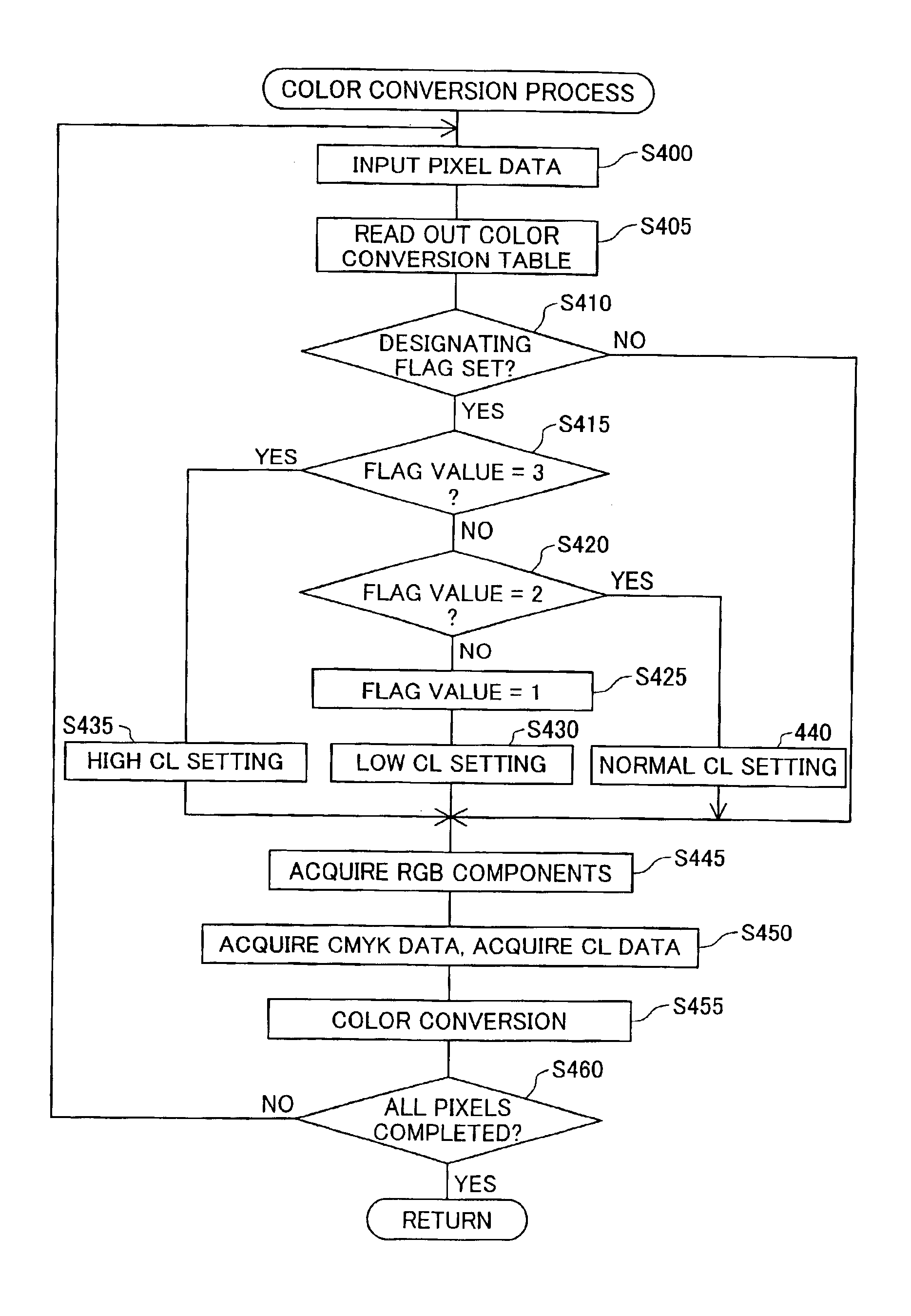
The enhancing ink amount VCL is set so that the total ink amount VT is at least a first predetermined non-zero value A. In areas where the colored ink amount VS is lower than the first predetermined value A, the enhancing ink amount VCL is set to a fourth predetermined non-zero value D. The fourth predetermined value D is greater than the first predetermined value A. Thus, even when the printing medium has low gloss, the enhancing ink amount VCL has the fourth predetermined value D in areas where the colored ink amount VS is low, allowing differences in gloss to be consistently minimized. Furthermore, the enhancing ink amount VCL is constant in areas where the colored ink amount VS is lower than the first predetermined value A, thus simplifying the cont...

example 1

B8. Example 1 of Second Quality Adjusting Mode:

FIGS. 13(a) and 13(b) show the relationship between the discharged amount of colored ink VS and the discharged amount of enhancing ink VCL in Example 1 of the second quality adjusting mode.

The enhancing ink amount VCL is set so that a VCL value for the colored ink amount VS of about 0% is lower than a VCL value for the VS value of about 100%. This reduces unevenness of coloring in image areas due to a difference in the colored ink amount VS. In areas where the colored ink amount VS is low, a small amount of enhancing ink is ejected to enhance color development, thereby conserving the enhancing ink amount VCL. The smaller amount of quality enhancing ink CL will prevent the printing medium from wrinkling, prevent the ejected ink from taking a longer time to dry, and conserve the quality enhancing ink. The enhancing ink amount VCL is also set so as not to decrease as the colored ink amount VS increases in this example. It is thus possible ...


PUM


Abstract

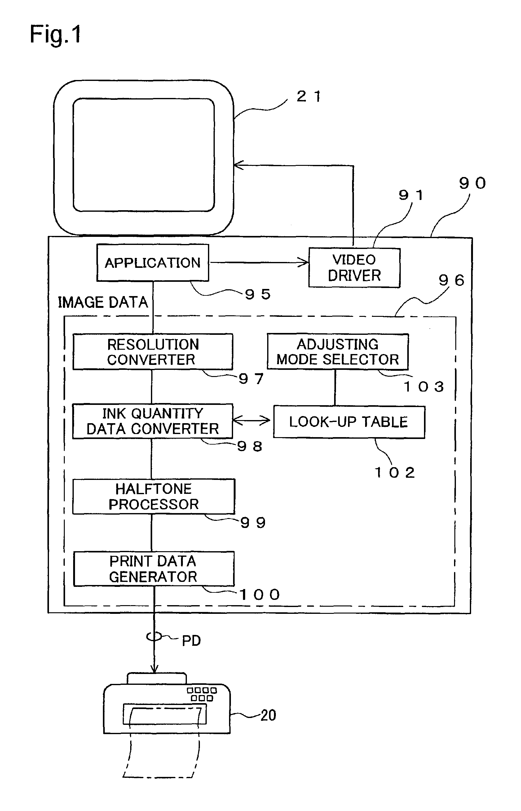
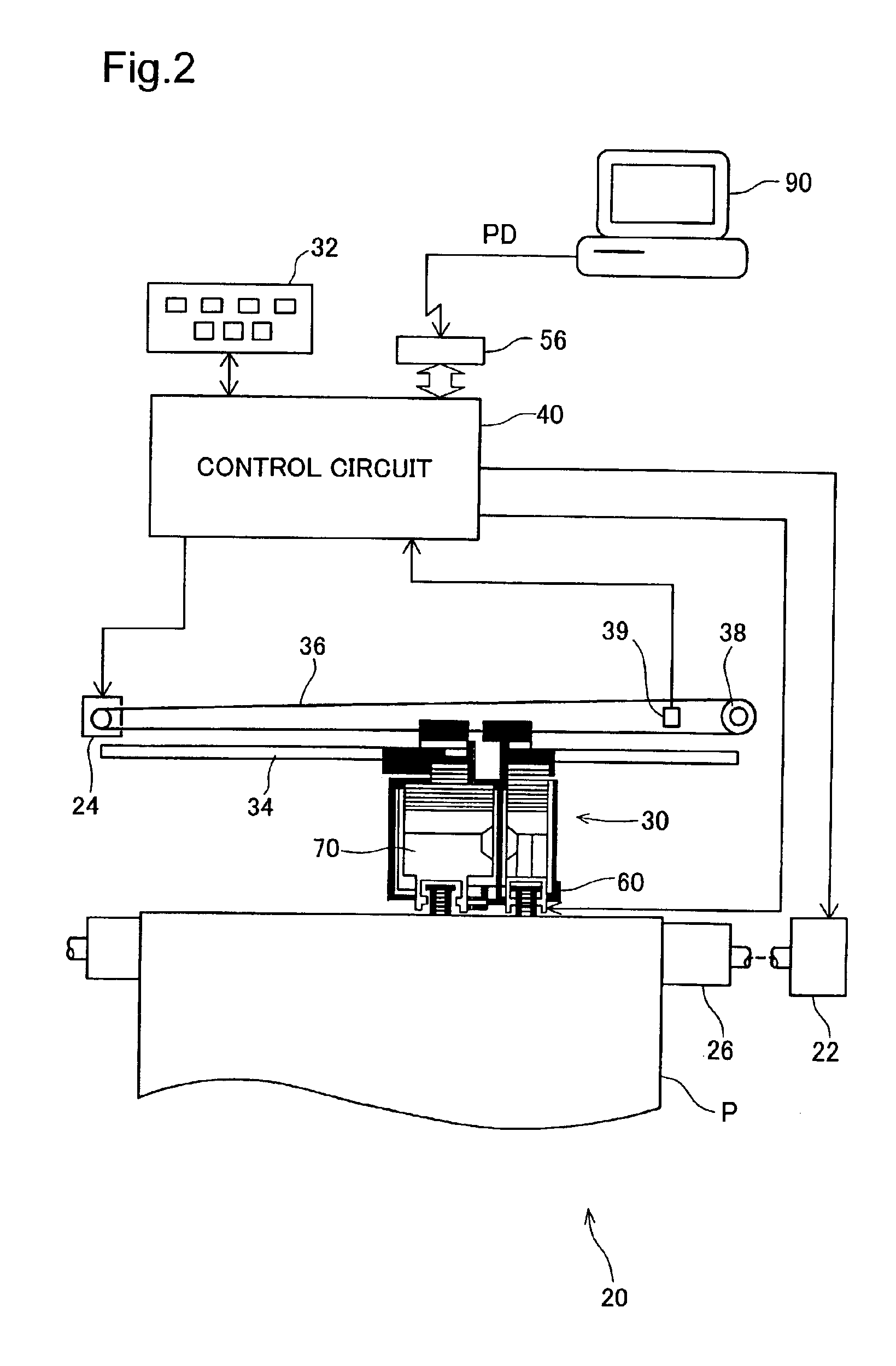
Image quality is improved by adjusting the ejection amount of quality enhancing ink based on the ejection amount of colored ink containing colorant. When a relatively high gross printing medium is used, the quality enhancing ink is ejected in an image area where virtually no colored ink is ejected, thereby improving unevenness in gloss within the print image. When a relatively low gross printing medium is used, on the other hand, the quality enhancing ink is ejected in an image area where the colored ink is ejected on virtually all pixels, thereby improving unevenness in color within the print image. The relationship between the ejection amounts of the quality enhancing ink and the colored ink may be modified by the user.

Description

BACKGROUND OF THE INVENTION1. Field of the InventionThe present invention relates to a printing device for printing images by ejecting a plurality of inks onto printing media.2. Description of the Related ArtIn recent years, ink jet printers have come to enjoy widespread use as image printing devices. Users may select desired print media from among a variety of available types for use in ink jet printers. Such print media include, for example, “glossy” paper having relatively high gloss, “plain” paper having relatively low gloss, matte paper, and so on.The amount of ink that is ejected onto printing media is determined by the image data that is to be printed. Greater amounts of ink are ejected in areas of low brightness, and lower amounts of ink are ejected in areas of higher brightness.When an image is printed on a printing medium of relatively high gloss, the gloss tends to be more intense in areas where more ink has been ejected. For example, when images of human figures are prin...

Claims


Application Information

Patent Timeline
Patent Type & Authority Patents(United States)
IPC IPC(8): B41J2/21
CPCB41J2/2114B41J2/17566
Inventor YAMAZAKI, SATOSHIYAMAMOTO, YUKO
Owner NEC CORP
Learn More