
Checking device and recording medium for checking the identification of an operator

a technology of operator identification and checking device, which is applied in the direction of unauthorized memory use protection, instruments, computer security arrangements, etc., can solve the problems of user forgetting where, unauthorized use of pen input portable terminals, and great risk, so as to facilitate remembering, easy to designate, and easy to remember the location

Inactive Publication Date: 2005-03-01
CASIO COMPUTER CO LTD
View PDF11 Cites 42 Cited by
  • Summary
  • Abstract
  • Description
  • Claims
  • Application Information

AI Technical Summary

Benefits of technology

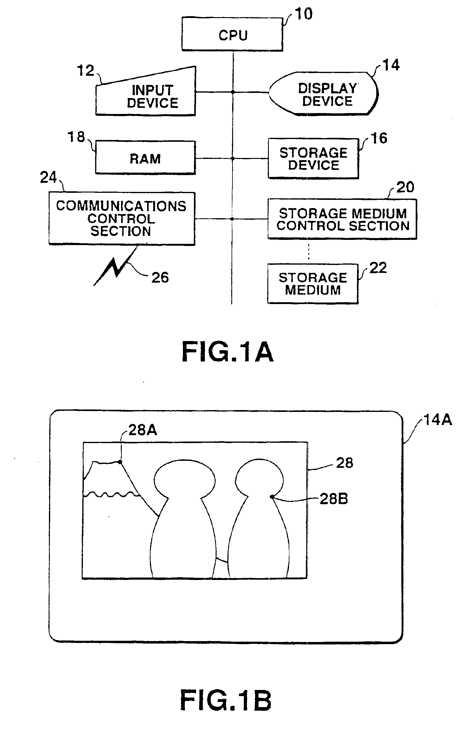
According to the checking device described above, checking is performed by the simple operation of designating at least one checking point on the image. In the case of the input of a password, there is the great risk that a person who is unauthorized to use the pen input portable terminal can easily guess the password from the motions of the user's hands or the touch pen at the time of the input of the password. However, the present invention does not entail such a risk, since the location of any point designated on the image is checked. If mere coordinates on the display screen which is not displaying such an image are to be designated, there will be the great possibility that the user may forget where they are. In the present invention, however, since the checking point as registered is a point on the image, the user can easily remember its location and therefore can easily designate it.
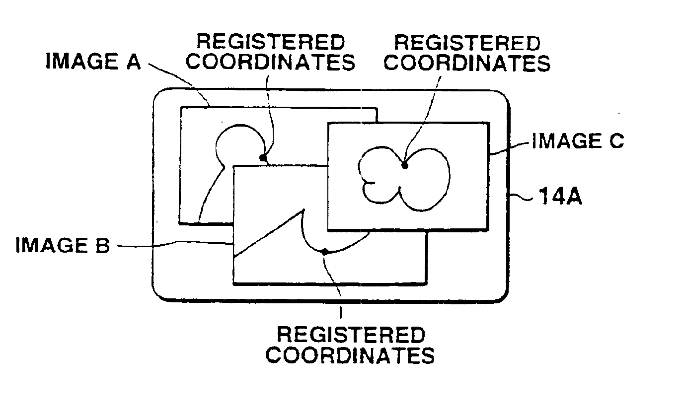
According to the present invention, a plurality of images may be displayed sequentially. In this case, checking is performed by the simple operation of designating a checking point on each of the images displayed sequentially. In the case of the input of a password, there is the great risk that a person who is unauthorized to use the pen input portable terminal can easily guess the password from the motions of the user's hands or the touch pen at the time of the input of the password. In the present invention, however, the locations of any points designated on the images are checked. Therefore, the present invention does not entail such a risk. If mere coordinates on the display screen which is not displaying such an image are to be designated, there will be the great possibility that the user may forget where they are. In the present invention, however, since the checking points as registered are points on the images, the user can easily remember their locations, and therefore can easily designate them.

Problems solved by technology

In the case of the input of a password, there is the great risk that a person who is unauthorized to use the pen input portable terminal can easily guess the password from the motions of the user's hands or the touch pen at the time of the input of the password.
If mere coordinates on the display screen which is not displaying such an image are to be designated, there will be the great possibility that the user may forget where they are.

Method used


Image

  • Checking device and recording medium for checking the identification of an operator
  • Checking device and recording medium for checking the identification of an operator
  • Checking device and recording medium for checking the identification of an operator

Examples


first embodiment

FIG. 1A is a diagram showing the structure of the pen input portable terminal employing the checking device according to the first embodiment of the present invention. In the illustration, reference numeral 10 denotes a CPU serving as a control section which controls the entirety of the pen input portable terminal. Reference numeral 12 represents an input device which includes a touch panel, a touch pen, etc. The touch panel is arranged at the display screen of a display device 14 such as an LCD display, for example. Reference numeral 16 denotes a storage device like a hard disk, a ROM or the like which stores images to be displayed, for example. Reference numeral 18 represents a RAM storing an image location table to be described later.

Reference numeral 20 denotes a storage medium control section which controls the storing and reading of data in and from a storage medium 22 such as a loaded floppy disk, an optical (magnetic) disk or the like. Reference numeral 24 represents a commu...

second embodiment

The second embodiment of the present invention will now be described.

The structure of the pen input portable terminal, which employs the checking device of the second embodiment, will not be explained hereinafter, since it is the same as that of the pen input portable terminal of the first embodiment. In the second embodiment, however, the image location table stored in the RAM 18 is as illustrated in FIG. 4A. More specifically, the image location table of the second embodiment stores, in association with each image window, its display position and its registered coordinates.

FIG. 5 is a flowchart for explaining the operation of the pen input portable terminal employing the checking device of the second embodiment. The storage device 16 or the storage medium 22 stores the programs for realizing the individual functions shown in the above flowchart, in the form of the program codes readable by the CPU 10.

According to the second embodiment, the CPU 10 selects the first image (image A) ...

third embodiment

The third embodiment of the present invention will now be described.

The structure of the pen input portable terminal, which employs the checking device of the third embodiment, will not be explained hereinafter, because it is the same as that of the pen input portable terminal of the first embodiment.

In the third embodiment, however, the RAM 18 stores, not the image location table, but a checking window table provided for each application, as illustrated in FIG. 4C. The checking window table stores a plurality of display icons and a registered icon in association with each window.

To be specific, when activating one application, a reference is made to the corresponding checking window table, and a plurality of icons are displayed in the head window as illustrated in FIG. 6A. When one of the icons displayed in the head window is selected and designated, it is determined whether the designated icon is identical with a registered one. In the case where the designated icon is identical w...


PUM


Abstract

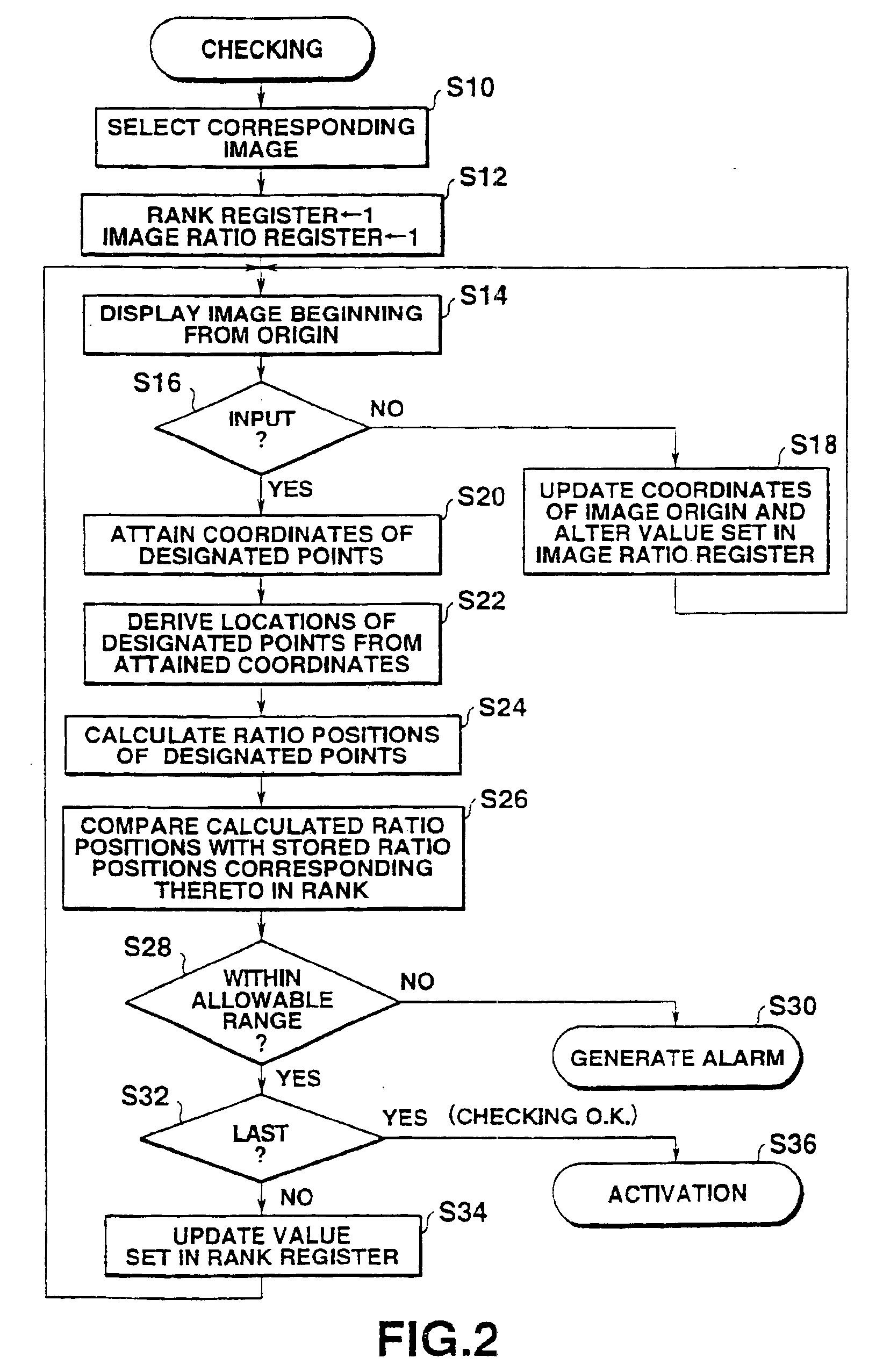
A CPU displays an image on a display device with reference to an image location table stored in advance in a RAM. When coordinates on the image are sequentially designated by an input device, the CPU sequentially compares the locations specified by the designated coordinates with those of checking points stored in the image location table. The CPU determines that the operator is authorized when errors or differences between the locations compared with each other are within an allowable range and when the order of designation of the coordinates is appropriate.

Description

TECHNICAL FIELDThe present invention relates to a checking device for checking the operator of information equipment, and a recording medium which stores programs for working a computer as such a checking device.BACKGROUND ARTOf late, information equipment like a personal computer, an input portable terminal, etc. has become widely used.In general, such information equipment is designed so that users can be restricted by checking passwords, in order to prevent information from being accessed by unauthorized persons.However, the input of passwords is troublesome. This is so especially in the case of a pen input portable terminal with no keyboard.DISCLOSURE OF INVENTIONIt is accordingly an object of the present invention to facilitate an operation for checking the operator who uses information equipment.According to one aspect of the present invention, there is provided a checking device for checking an operator, comprising:storage means for storing in advance an image and a location ...

Claims


Application Information

Patent Timeline
Patent Type & Authority Patents(United States)
IPC IPC(8): G06F1/00G06F21/00G06F21/31G06F21/36
CPCG06F21/36
Inventor SUZUKI, HIDEO
Owner CASIO COMPUTER CO LTD
Learn More