High speed scanning or steering device

a scanning or steering device, high-speed technology, applied in the direction of instruments, machine supports, other domestic objects, etc., can solve the problems of requiring devices may require high resonant stiffness when, and manufacturing costs are an issue in certain high-volume products, so as to prevent undesirable bending forces and prevent undesirable translation movements or resonances

Inactive Publication Date: 2005-03-01
MOORE JAMES DOUGLAS
View PDF7 Cites 2 Cited by
  • Summary
  • Abstract
  • Description
  • Claims
  • Application Information

AI Technical Summary

Benefits of technology

In accordance with the present invention, there is provided a pivoting central element and mounting stem, two orthogonally arranged and offset “V” shaped flexure elements and two orthogonal moving elements connected to a base structure via parallel motion flexures which restrict motion to a single axis. The parallel motion flexures serve to prevent undesirable bending forces in the linear actuators which are sometimes made of fragile ceramic materials, while at the same time preventing undesirable translation movements or resonances. The central tilting element and mounting stem are restrained in two translation axes by the two “V” shaped and offset flexural elements connecting the central element to the respective axially driven elements. The offset distance between the planes of the “V” shaped elements determines the mechanical multiplication of the actuator movement. A third type of orthogonal rod flexure restrains the remaining axis of translation motion, namely a translation of the central pivoting element in a direction orthogonal to the “V” shaped flexural elements, referred to herein as bipod elements. Piezoelectric, electrostrictive or similar actuators operate either separately or simultaneously to drive the central element in the two remaining unrestrained tilting axes, via the offset bipod flexures, producing tilt in any commanded direction. A sealing cover containing an elastic diaphram to accommodate tilt may be added to the base structure as required for protection in harsh environments.

Problems solved by technology

It will be seen that such existing or previously patented devices generally sacrifice stiffness for increased range of motion.
Generally the inventor is forced to make some trade-off which might be undesirable for a range of applications.
Such devices may require high resonant stiffness when motionless to maintain a desired position in the presence of external vibrations in the environment, such as might be induced by gusting winds or adjacent vibrating machinery.
Manufacturing cost is an issue in certain high volume products.
To maximize tilting range a device may require very thin flexural elements which are complex and difficult to manufacture by common methods due to bending of relatively long and thin elements from tool cutter forces.
Electrical discharge machining (EDM) methods eliminate cutting tool forces, however large quantities cannot be economically machined using this method owing to the slow rate of material removal.
These conventional devices exhibit fair stiffness but with limited range.
Voice coil actuators, however, are less compact than are electrostrictive or piezoelectric actuators and have no inherent stiffness.
Therefore they must be stiffened through electrical damping means with a corresponding increase in complexity of controls and loss of electrical efficiency.
Patel, in U.S. Pat. No. 5,550,669, discloses a complex device claiming stiffness and range of motion as apparent primary objectives, but not simplicity or ease of manufacture.
U.S. Pat. No. 4,973,145 employs relatively long rod flexure supports arranged in a conical fashion, enabling considerable tilt and low hysteresis, but permitting low frequency tilting resonances due to lack of restraints to control the six possible axes of motion in a mechanical structure.
Tilting resonances could be eliminated by electronic damping of the peripheral actuators, but the device seems unsuited to high speed operation.
From the foregoing discussion therefore, it is clear that prior art inventions and apparatus do not ideally meet the competing requirements of high stiffness, high range, low hysteresis, producibility, and specification adaptability.

Method used


Image

  • High speed scanning or steering device
  • High speed scanning or steering device
  • High speed scanning or steering device

Examples


Embodiment Construction

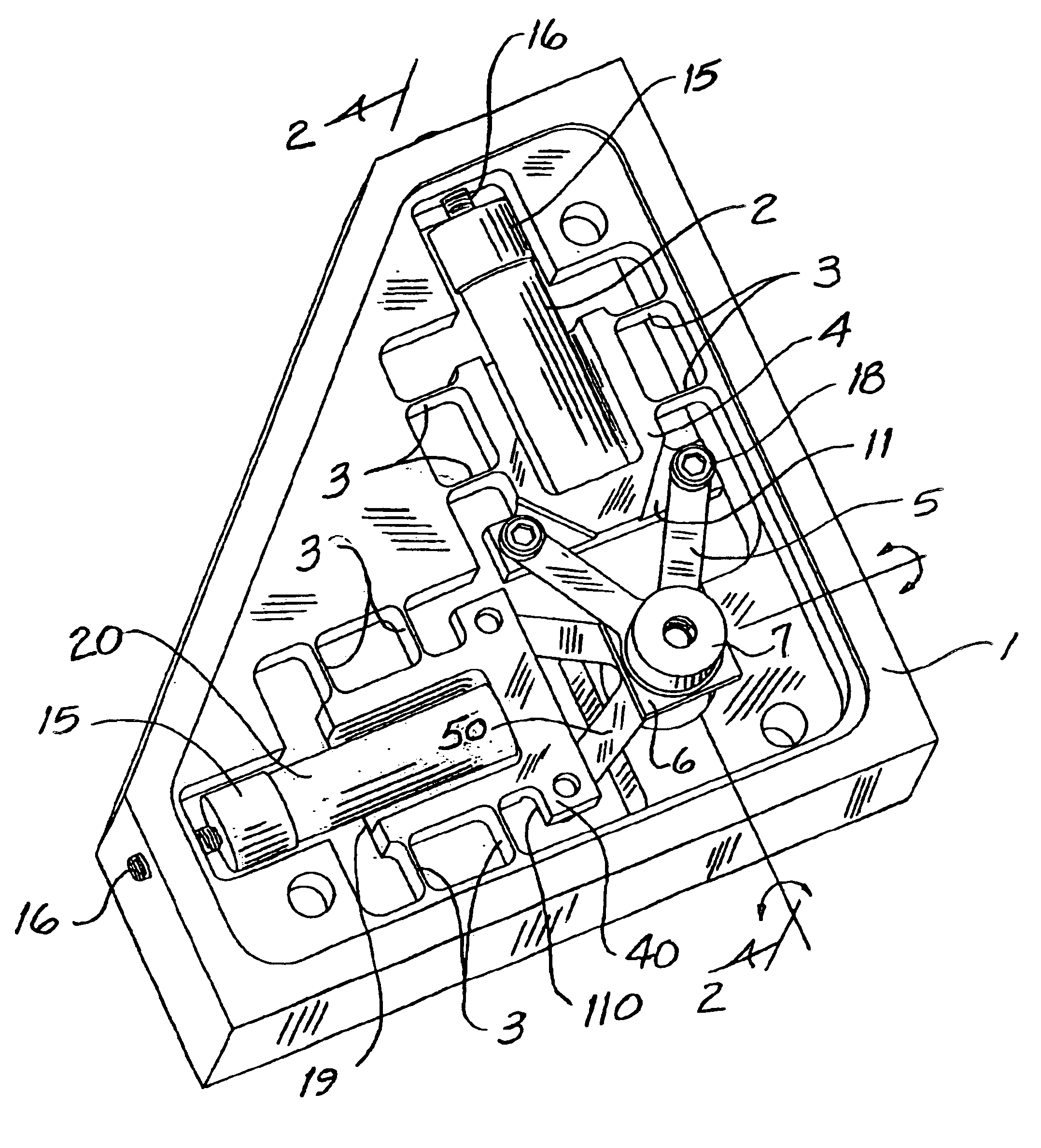
FIG. 1 is a perspective view of the assembled inventive device with an optional cover removed.

FIG. 2 is a cross sectional view of the device shown in FIG. 1, taken along lines 2—2 thereof.

As seen in FIG. 1, a first relatively wide pocketed translating frame element 4 and a second like frame element 40 are disposed orthogonally within a base structure 1. Each frame element 4 and 40 is restrained in five of six possible degrees of mechanical freedom by a set of parallel motion flexures 3. The parallel motion flexures 3 stiffly restrains the pocketed translating frame elements 4 and 40 in all possible degrees of freedom except one desired translation axis. Each of the translating frame elements 4 and 40 employ an integral shear stiffener 19 across the pockets in frame elements 4 and 40 to further reduce undesired flexibility and maximize resonant frequency. Each translating frame element 4 and 40 is acted upon by a first electromotive actuator 2 and a second like actuator 20, respectiv...


PUM


Abstract

A high speed, high displacement steering device used for rapid mirror or light source pointing consisting of a pivoting central element and mounting stem, two orthogonally arranged and offset “V” shaped flexure elements connected to two orthogonally arranged moving elements which are driven by electromotive actuators. Said moving elements are connected to a base structure via parallel motion flexures which serve to prevent undesirable bending forces in the linear actuators, while at the same time preventing undesirable translation movements, cross coupling of motion and resonances. A third type of orthogonal rod flexure restrains the remaining axis of translation motion, namely a translation of the central pivoting element in a direction perpendicular to the tilting axes. Piezoelectric, electrostrictive or similar actuators operate either separately or simultaneously to drive the central element in the only two remaining unrestrained tilting axes, via the offset “V” shaped flexures, producing tilt in any commanded direction. A sealing cover containing an elastic diaphragm to accommodate tilt may be added to the outer support structure as required for protection in harsh environments.

Description

FIELD OF THE INVENTIONThe present invention relates to devices for multiplying mechanical motion and, more particularly, to electromechanical devices which enable high speed leveraged tilting movements from short-travel linear actuator movements.BACKGROUND OF THE INVENTIONElectromechanical motion multiplying devices, using stiff, compact, short-travel, low inertia actuators are used in a wide range of systems where high speed or high resolution mechanical movement is essential such as in laser beam targeting, telescope light beam tracking, vibration control, and scanning applications. These devices typically employ piezoelectric, electrostrictive, or electromagnetic actuators which act either directly or via leveraging means.Certain optical systems require high speed low inertia, low hysteresis tilting devices for the precision 2-axis control of mirrors, optics or primary light beam sources. Some applications require both a large range of motion and high stiffness with minimal undes...

Claims


Application Information

Patent Timeline
Patent Type & Authority Patents(United States)
IPC IPC(8): G02B26/08G02B7/182
CPCG02B26/0816G02B7/1821
Inventor MOORE, JAMES DOUGLAS
Owner MOORE JAMES DOUGLAS
Why Eureka
Try Eureka