Pneumatic tire and a process for mounting the tire onto vehicle

a technology of pneumatic tires and tires, which is applied in the field of pneumatic tires, can solve the problems that the braking performance inherent in tires cannot reach a satisfactory level, and achieve the effect of effectively compensating such forces and advantageously improving the stability of vehicle braking postur

Inactive Publication Date: 2005-03-01
BRIDGESTONE CORP
View PDF9 Cites 9 Cited by
  • Summary
  • Abstract
  • Description
  • Claims
  • Application Information

AI Technical Summary

Benefits of technology

It is, therefore, an object of the invention to provide a high-performance pneumatic tire capable of effectively improving the braking performance of the vehicle, particularly the stability of vehicle posture in the sudden braking suddenly and a process for mounting such a tire onto the vehicle.
In such a tire, the shearing rigidity in the circumferential direction in the application of the braking force is higher in the sidewall portion located at the outside of the vehicle than in the sidewall portion located at the inside of the vehicle, so that the shearing deformation amount of the sidewall portion located at the inside of the vehicle becomes larger than that of the sidewall portion located at the outside of the vehicle in the application of the braking force to the tire and the ground contact area of the tread portion is larger in a part of the tread portion located at the inside of the vehicle than that in a part located at the outside of the vehicle. Thus, right- and left-wheeled tires symmetrically arranged on both side of the vehicle with respect to a center line in a widthwise direction thereof create a force of intending to change into an inward direction based on a difference of frictional force between the tire and the road surface in addition to a difference of rotating radius necessarily caused in the braking of the tire. However, such a force is usually offset by the interaction between the left and right tires, and as a result, the occurrence of yaw moment around the center of gravity in the vehicle is effectively controlled to sufficiently prevent the disorder of the vehicle posture in the braking. The term “yaw moment” used herein means a moment of yawing around a straight line perpendicular to the road surface among the yawings caused in the vehicle running along the road surface.
In this way, absolute values of the forces changing into the inward direction created in the left- and right-wheeled tires are substantially made equal, whereby the disorder of the vehicle posture in the braking of the vehicle is more effectively prevented.
Moreover, in case of arranging one or more turn-up reinforcing layers wound around the bead core, a portion of the turn-up reinforcing layer located at the innermost side in the widthwise direction of tire is the innermost reinforcing layer. Because, the strength in the turn-up reinforcing layer wound around the bead core is increased by turning to enhance the reinforcing effect. Therefore, when the turn-up reinforcing layer is arranged so as to render into an inner layer, the reinforcing effect is more enhanced by the synergistic action with the above tension increasing effect.
According to the invention, the stability of vehicle posture in the braking can advantageously be improved because the shearing rigidities in the circumferential direction of the respective tire zones are made substantially symmetrical in the pair of left- and right-wheeled tires with respect to the center line of the vehicle in the widthwise direction to sufficiently equalize forces changing in the. inward direction created in the pair of the left- and right-wheeled tires and effectively offset such forces.

Problems solved by technology

However, it is an actual state that the braking performance inherent to the tire does not reach to a satisfactory level including the stability of vehicle posture in the sudden braking.

Method used


Image

  • Pneumatic tire and a process for mounting the tire onto vehicle
  • Pneumatic tire and a process for mounting the tire onto vehicle
  • Pneumatic tire and a process for mounting the tire onto vehicle

Examples


Embodiment Construction

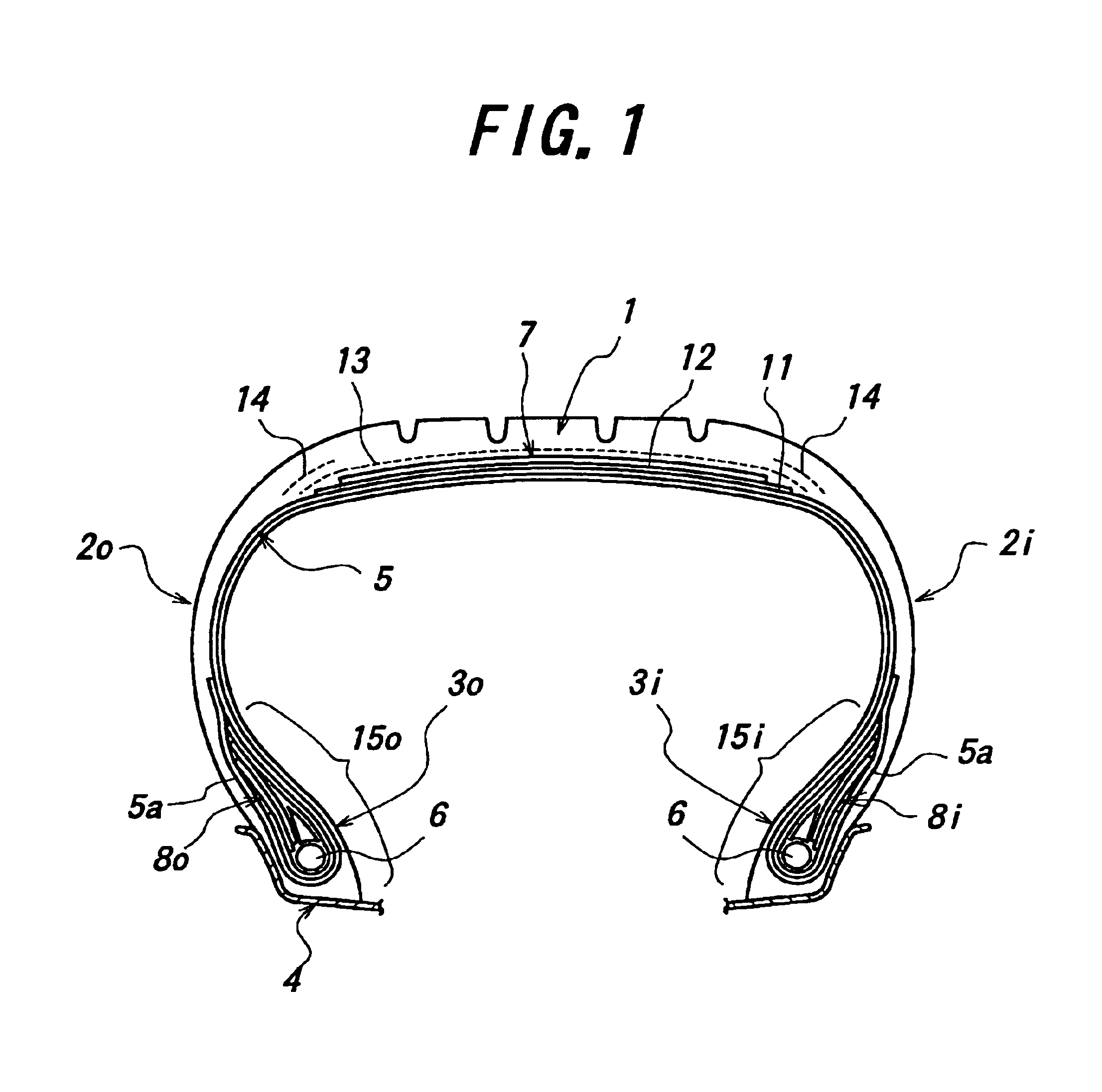
In FIG. 1 is shown a diagrammatically section view of an embodiment of the pneumatic tire according to the invention at a state of being mounted onto a rim, in which numeral 1 is a tread portion, numerals 2i and 2o sidewall portions extending inward from the both sides of the tread portion 1 in a radial direction, numerals 3i and 3o bead portions continuously connected to inner ends of the sidewall portions 2i, 2o in the radial direction, and numeral 4 a wheel rim seated with the bead portions 3i, 3o.

Moreover, these portions 1, 2, 3 are reinforced between bead cores 6 embedded in the respective bead portions 3i, 3o by a carcass 5 comprised of at least one ply containing organic fiber cords such as polyester cords, nylon cords and the like arranged in the radial direction, while each side portion of the carcass 5 is wound and fixed around the bead core 6 upward in the radial direction. And also, the tread portion 1 is reinforced with a belt 7 superposed on an outer peripheral side o...


PUM


Abstract

A pneumatic tire comprises a tread portion, a pair of sidewall portions, a pair of bead portions, a carcass, a belt, and a reinforcing member arranged in a tire zone including at least the sidewall portion, wherein a shearing rigidity in the circumferential direction of the reinforcing member is made larger at a first tire zone located at an outside of the vehicle than at a second tire zone located at an inside of the vehicle in the same tire at a posture of mounting the tire onto a vehicle.

Description

BACKGROUND OF THE INVENTION1. Field of the InventionThis invention relates to a pneumatic tire capable of improving a braking performance in a vehicle, particularly a stability of vehicle posture in the sudden braking and a process for mounting such a tire onto the vehicle.2. Description of Related ArtIn order to meet a social demand for more improving safety performances of the vehicle, ABS (antilock braking system or a system for preventing the wheels from locking in the sudden braking) tends to be mounted onto recent vehicles, whereby an action of avoiding danger can be carried out even in the sudden braking.On the other hand, the braking performance of the vehicle is largely influenced by performance of the tire as a contact point between the road surface and the vehicle, so that various studies have been made for improving the braking performance in the tire. However, it is an actual state that the braking performance inherent to the tire does not reach to a satisfactory level ...

Claims


Application Information

Patent Timeline
Patent Type & Authority Patents(United States)
IPC IPC(8): B60C9/17B60C3/06B60C3/00B60C9/02B60C19/00B60C5/00B60C15/06
CPCB60C3/06B60C9/17B60C19/001Y10T152/10504Y10T152/10819Y10T152/10864Y10T152/10828
Inventor MATSUMOTO, HIROYUKIMAEHARA, DAISUKE
Owner BRIDGESTONE CORP
Why Eureka
Try Eureka