
Method for managing a photovoltaic solar module and a photovoltaic solar module

a technology of photovoltaic solar modules and solar cells, applied in the direction of photovoltaics, electric variable regulation, batteries, etc., can solve the problems of appreciable power loss, partial shadowing of the surface equipped with solar cells, and limited curren

Inactive Publication Date: 2005-02-22
SAINT-GOBAIN GLASS FRANCE
View PDF18 Cites 39 Cited by
  • Summary
  • Abstract
  • Description
  • Claims
  • Application Information

AI Technical Summary

Benefits of technology

Starting from the automatic control of power of a solar module as a function of incident light, already known per se, the invention proposes that a partial shadow be detected automatically and that a shunt possibly be connected by comparing the incident light at at least two different locations of a flat module, which shunt makes it possible to prevent the current from entering the module (or the module part) associated with the relevant shadow. Thus, in practice the latter is “extracted from the array of modules” and the current which flows in the solar cells or additional modules connected in series and which are not in shadow is no longer blocked. Consequently, although the electric power of the disconnected module disappears for the duration of the shadowing or of the connection of the shunt, the instantaneous power of the other solar cells or of the other modules remains available to its full extent.
Preferably, one of the two conductors is completely disconnected at the same time as the poles of the disconnected module, or of the disconnected part of the module, are bypassed. In this way the voltage which is still delivered by other modules is prevented from being applied to the module or the part of module disconnected and is prevented from possibly overcharging this module or this part. This separation may be effected easily by means of a contactor / inverter.
An important advantage of this configuration of the solar module resides in that the solar detection cells may be solar cells of the same structure as those used for the production of current. Consequently, the solar modules can also be made as a surface of large dimensions by the thin-film technique, in addition to conventional crystalline technology. This has the advantage of subsequently being able to separate the individual solar cells from one another by structuration or splitting of the continuous films according to the state of the art, and in particular also of being able to separate the detection cells. It is only when the electrical connections are laid that the detection cells need to be treated separately. Their external connections may possibly have to be laid in a separate manner from those of the other solar cells (which have to be connected together in series).

Problems solved by technology

When using photovoltaic installations exhibiting solar modules of large dimensions, the variable position of the sun in the course of the day always gives rise to partial shadowings of the surfaces equipped with solar cells, which are caused for example by neighboring constructions, antennas, trees, etc.
Even when the surface in shadow is a small area, these passing shadows may give rise to appreciable losses of power of the system as a whole consisting of several identical modules.
Furthermore, the current is likewise limited by other modules connected in series.
Strong local shadow on a small number of solar cells (1 to 5% of the total surface area) may then result in a loss of power of 75% over the system as a whole.
This device should moreover not limit the negative consequences of partial shadows, but render the relevant solar module inoperative if it has for example been dismantled in an unauthorized manner.

Method used


Image

  • Method for managing a photovoltaic solar module and a photovoltaic solar module
  • Method for managing a photovoltaic solar module and a photovoltaic solar module
  • Method for managing a photovoltaic solar module and a photovoltaic solar module

Examples


Embodiment Construction

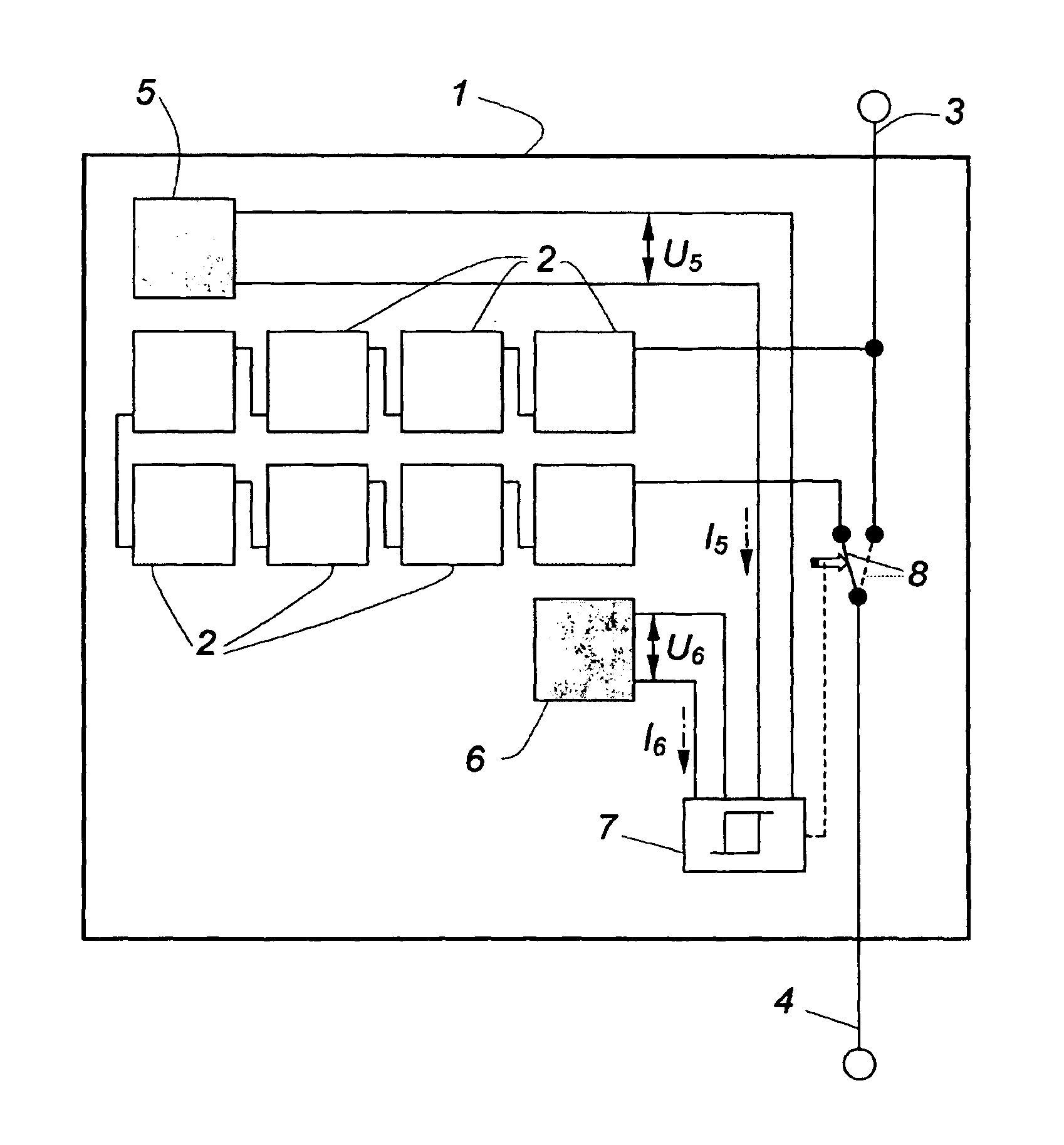
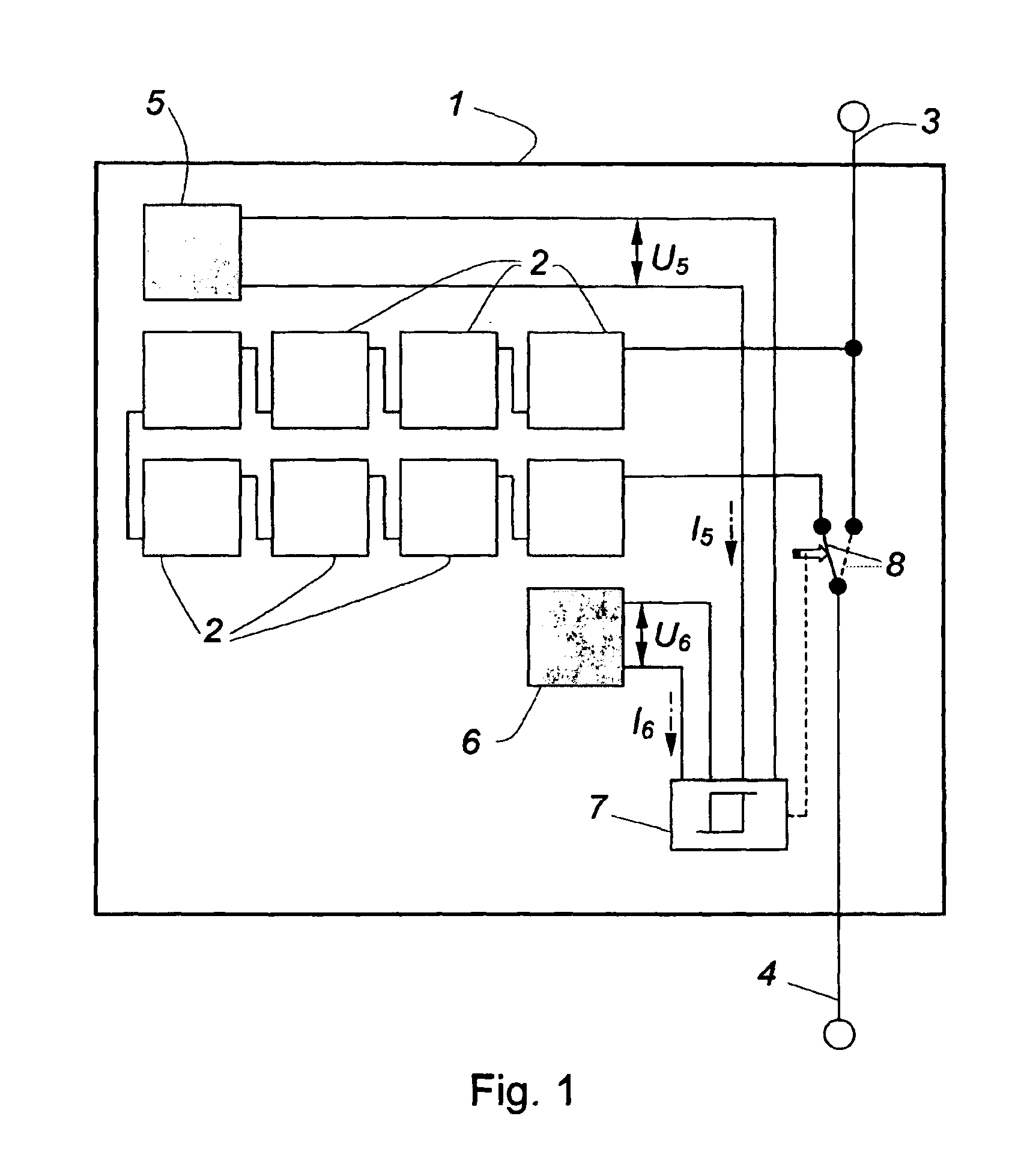
In FIG. 1, a plurality of solar cells 2 are connected together in a manner known per se in a photovoltaic solar module 1. The solar module 1 is moreover equipped with two external connections 3 and 4 to which, when operational, the output voltage of the arrangement of solar cells is applied or from which the electric power of the solar module 1 is tapped off. The shunt diodes already mentioned, which may be associated with individual solar cells or with groups of solar cells, have not been represented here for the sake of simplicity.

In most applications, several of these solar modules 1 are in turn connected together electrically in series so as thereby to obtain service voltages of several hundred volts. This implies that all of the current of the solar modules connected upstream must also pass through the module represented here. So if only the latter is in shadow, even partially, or if the incident light decreases on this module alone, its output power decreases. Its resistance i...


PUM


Abstract

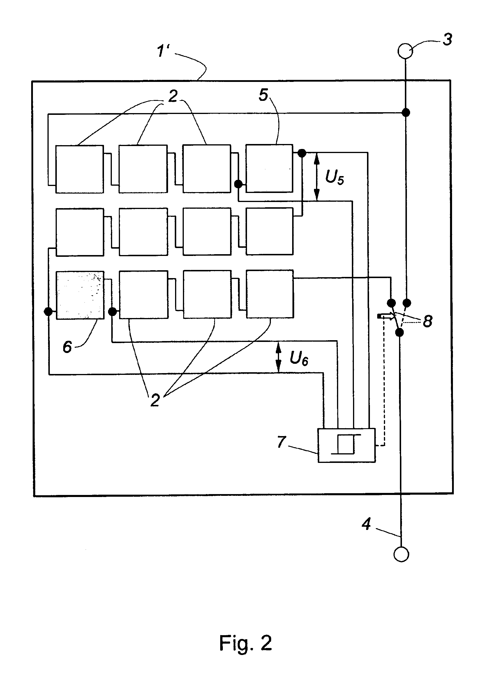
In a solar module (1) comprising a plurality of individual solar cells (2) connected together electrically in series, with at least one solar cell (5, 6) exposed to the same conditions and not linked to the other solar cells, which serves as sensor of the instantaneous incident light on the solar module and with a switching device (8) able to be slaved at least indirectly to the sensor so as to act on the output electric power of the solar module, according to the invention, at least two solar cells (5, 6), which are disposed a large distance apart, are provided as sensors whose output voltages or currents are conveyed to an evaluation circuit (7) and are compared with one another by the latter, and the evaluation circuit (7) connects by means of the switching device (8) a shunt which bypasses the series circuit of the solar cells (2) of the solar module (1) when a difference which exceeds a threshold value exists between the outputs of the two sensors.

Description

FIELD OF THE INVENTIONThe invention relates to a process for managing a photovoltaic solar module as a function of incident light, and a photovoltaic solar module. The voltaic solar module comprises a plurality of individual solar cells connected together electrically in series, with at least one solar cell exposed to the same conditions, which serves as sensor of the instantaneous incident light on the solar module and with a switching device able to be slaved at least indirectly to the sensor so as to act on the output electric power of the solar module.BACKGROUND OF THE INVENTIONWhen using photovoltaic installations exhibiting solar modules of large dimensions, the variable position of the sun in the course of the day always gives rise to partial shadowings of the surfaces equipped with solar cells, which are caused for example by neighboring constructions, antennas, trees, etc. Even when the surface in shadow is a small area, these passing shadows may give rise to appreciable lo...

Claims


Application Information

Patent Timeline
IPC IPC(8): H01L31/05H01L31/042
CPCH01L31/02021Y02E10/50Y10S136/291Y10S136/293Y10S136/29Y10S323/906Y02E10/56H02J7/35
Inventor ERBAN, CHRISTOF
Owner SAINT-GOBAIN GLASS FRANCE
Learn More