
Dual clutch transmission unit for a motor vehicle

a transmission unit and motor vehicle technology, applied in mechanical actuators, mechanical apparatus, gearing, etc., can solve the problem of relatively complex known solutions described abov

Inactive Publication Date: 2005-02-22
FAB ITAL MAGNETI MARELLI SPA
View PDF9 Cites 14 Cited by
  • Summary
  • Abstract
  • Description
  • Claims
  • Application Information

AI Technical Summary

Benefits of technology

The object of the present invention is to provide a dual clutch transmission unit for a motor vehicle which makes it possible simply and economically to resolve the above-mentioned problems.

Problems solved by technology

The known solutions described above are relatively complex, as they include a relatively large number of components needed to actuate and control the two clutches independently.

Method used


Image

  • Dual clutch transmission unit for a motor vehicle
  • Dual clutch transmission unit for a motor vehicle
  • Dual clutch transmission unit for a motor vehicle

Examples


Embodiment Construction

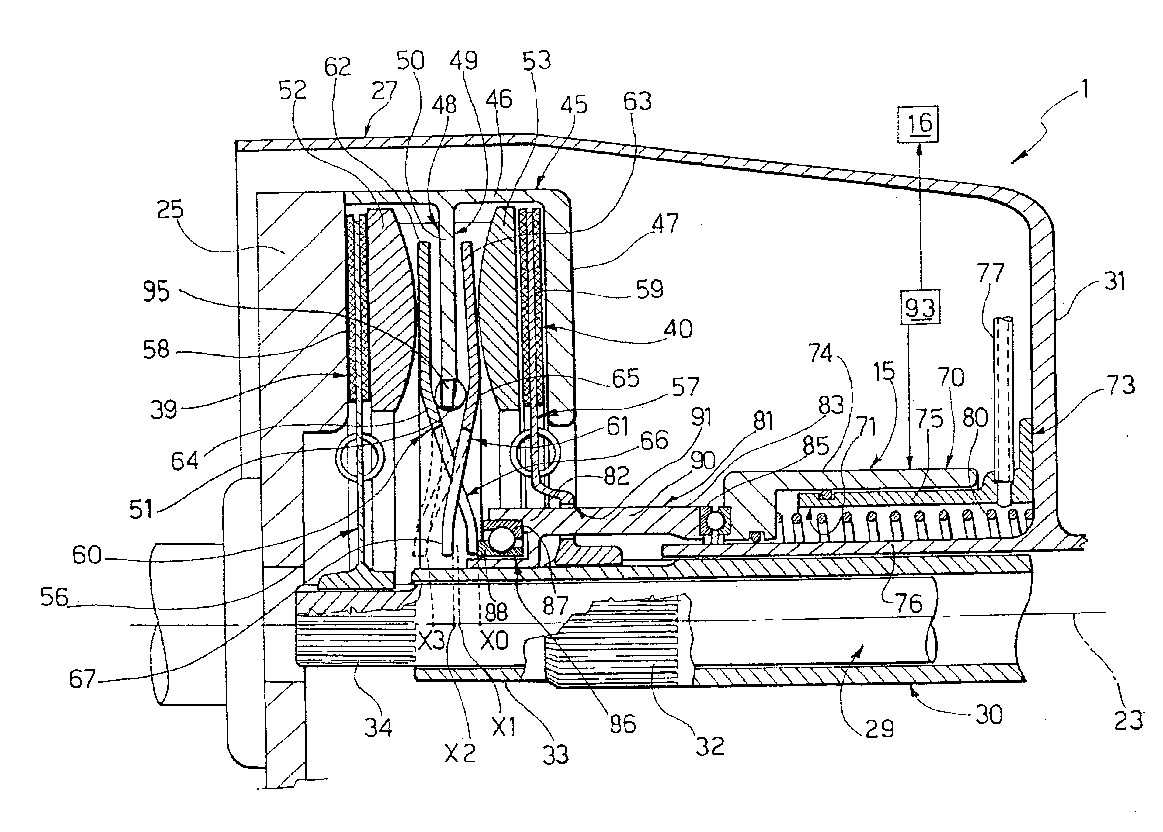
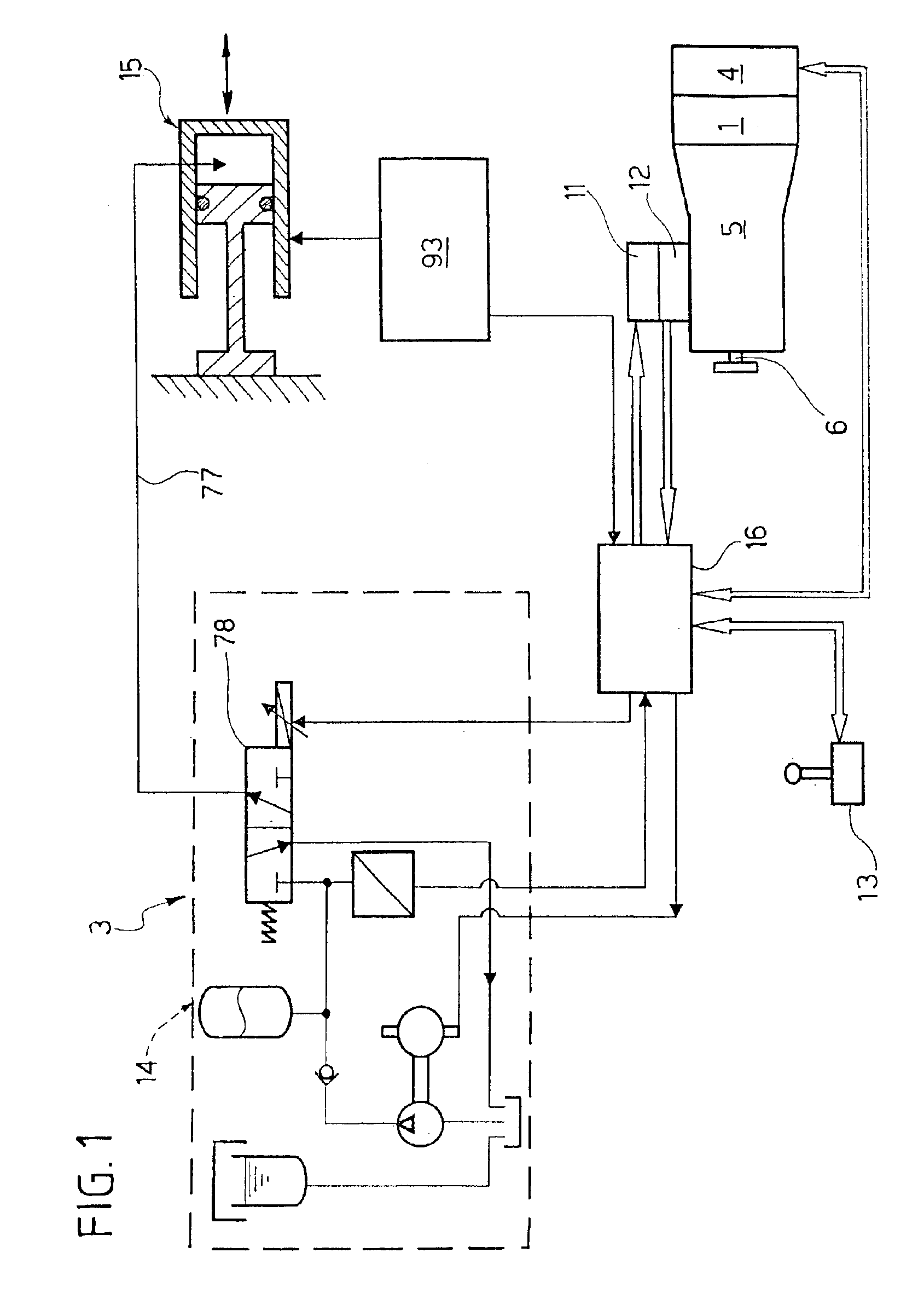
In the accompanying drawings, a dual clutch transmission unit for a motor vehicle 3 (shown diagrammatically in FIG.1) provided with an internal combustion engine 4 and a gear change 5 is shown by 1.

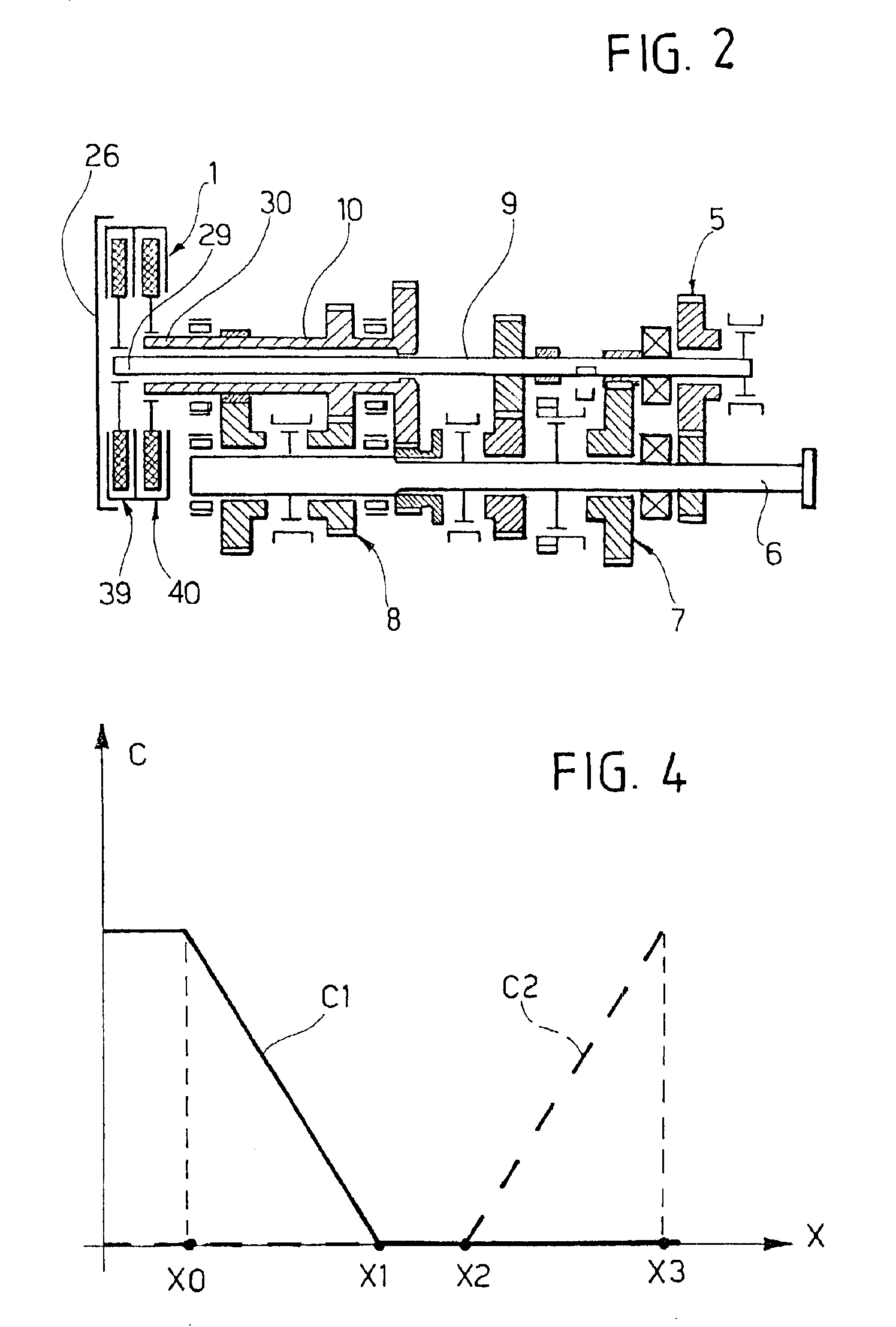
The gear change 5, of known type and shown diagrammatically, has a discrete number of gears each corresponding to a relative transmission ratio and comprises a movement output shaft 6 adapted to drive in rotation the drive wheels of the motor vehicle 3, and two movement input shafts 9, 10 (FIG. 2) which are coaxial and housed one within the other. The shafts 9, 10 are coupled to the shaft 6 by respective trains 7, 8 of toothed wheels associated with respective ranks of gears, for instance even gears and odd gears respectively.

Each rank of gears is controlled by a relative engagement actuator device 11, 12 (FIG. 1) in accordance with the setting imposed by the driver by means of a lever 13 disposed in the passenger space of the motor vehicle 3.

In FIG. 1, the motor vehicle 3 further compris...


PUM


Abstract

A dual clutch transmission unit for a motor vehicle is adapted to transmit the movement to an automatic gear change provided with two ranks of gears; the transmission unit has a rotary movement input member adapted to be driven in rotation by the engine of the motor vehicle and two output shafts which are adapted to be rigidly connected to respective input shafts of the gear change and bear respective clutch devices which are adapted to receive the movement from the rotary member and are each associated with a relative rank of gears of the gear change; one of the clutch devices is disengaged and the other is engaged in sequence by an actuator device provided with a single actuator and a movement sleeve coaxial with one another.

Description

The present invention relates to a dual clutch transmission unit for the transmission of movement, in a motor vehicle, from the engine to an automatic gear change provided with two ranks of gears, in particular a rank of even gears and a rank of odd gears.These automatic gear changes make it possible to cancel out the lack of traction on the wheels during gear changes, as a result of the fact that they are actuated by two clutches which are controlled such that they transmit the movement selectively, one for the even gears and the other for the odd gears.BACKGROUND OF THE INVENTIONAccording to known solutions, the two clutches are of the oil-bath type and are fully independent from one another, i.e. they are actuated by dedicated and separate devices, each of which comprises a relative actuator, a relative control device driven for instance by fluid supply and electrovalves in the case in which the actuator is of the oil-hydraulic type, and a relative sensor for controlling the stro...

Claims


Application Information

Patent Timeline
Patent Type & Authority Patents(United States)
IPC IPC(8): F16H3/00F16D48/00F16D48/06
CPCF16H3/006F16D48/062F16D48/064F16D2048/0269F16D2500/3026F16D2500/31466F16D2500/50825F16D2500/7041F16D2500/70458F16D2500/7061
Inventor TORNATORE, GIOVANNISOLA, CESAREGIROLA, FABRIZIO
Owner FAB ITAL MAGNETI MARELLI SPA
Learn More