Eureka AIR delivers breakthrough ideas for toughest innovation challenges, trusted by R&D personnel around the world.

Brake positioning system

Inactive Publication Date: 2005-02-22
SAWSTOP HLDG LLC
View PDF353 Cites 189 Cited by
  • Summary
  • Abstract
  • Description
  • Claims
  • Application Information

AI Technical Summary

Problems solved by technology

In a system that utilizes a brake to stop the machine, the spacing between the brake and the portion of the machine to be braked—typically a cutter or saw blade—can lead to significant delays in brake action.

Method used


Image

  • Brake positioning system
  • Brake positioning system
  • Brake positioning system

Examples


Embodiment Construction

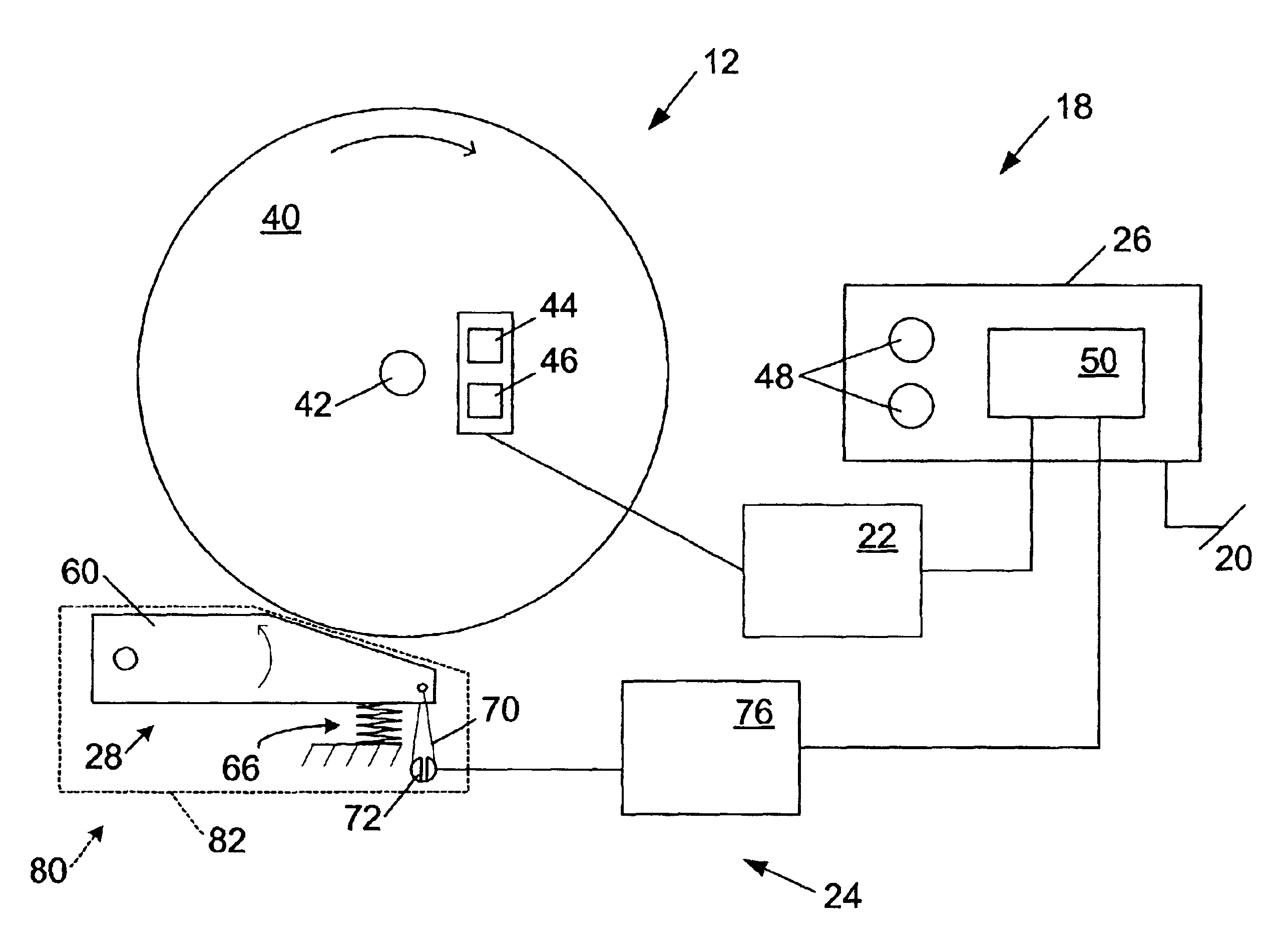
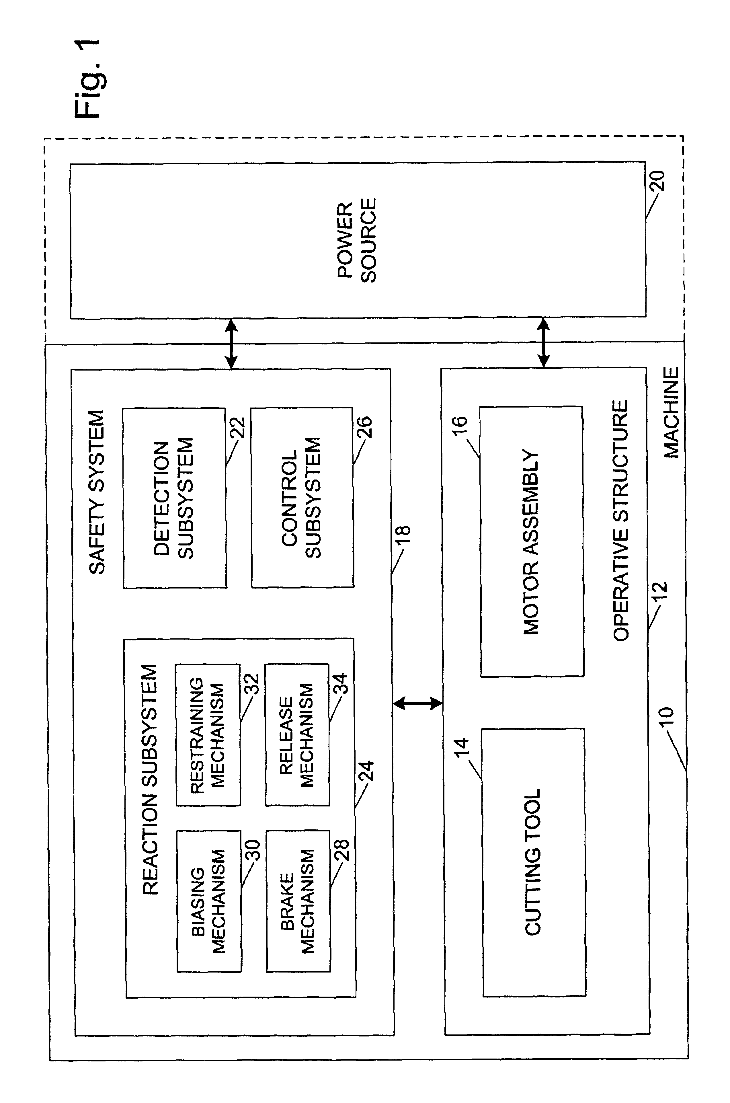
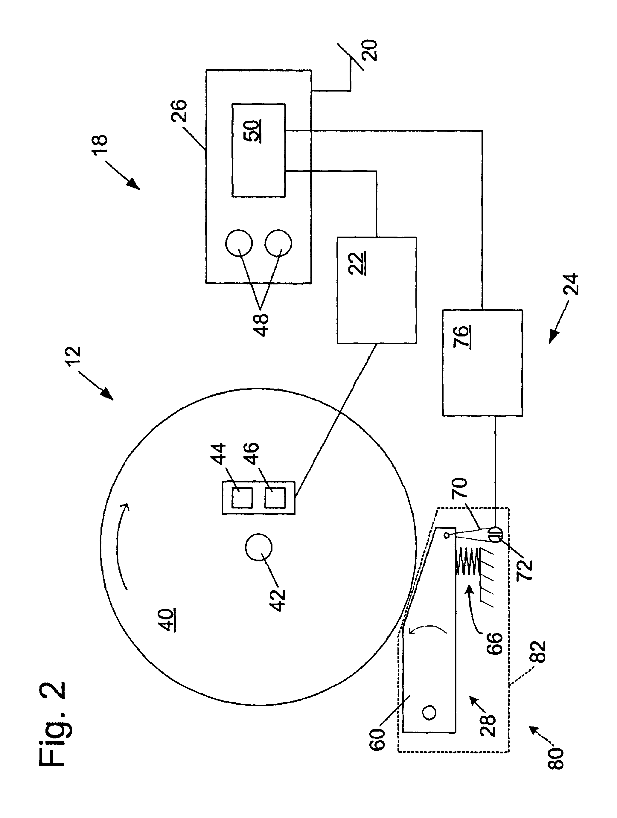
A machine that may incorporate a brake positioning system according to the present invention is shown schematically in FIG. 1 and indicated generally at 10. Machine 10 may be any of a variety of different machines adapted for cutting workpieces, such as wood, including a table saw, miter saw (chop saw), radial arm saw, circular saw, band saw, jointer, planer, etc. Machine 10 includes an operative structure 12 having a cutting tool 14 and a motor assembly 16 adapted to drive the cutting tool. Machine 10 also includes a safety system 18 configured to minimize the potential of a serious injury to a person using machine 10. Safety system 18 is adapted to detect the occurrence of one or more dangerous conditions during use of machine 10. If such a dangerous condition is detected, safety system 18 is adapted to engage operative structure 12 to limit any injury to the user caused by the dangerous condition.

Machine 10 also includes a suitable power source 20 to provide power to operative st...


PUM


Abstract

A saw is disclosed having a detection system adapted to detect a dangerous condition between a person and a saw blade, and a brake adapted to stop the saw blade in response to detection of the dangerous condition. The saw further includes a brake positioning system that allows the brake to be positioned in at least two different operable positions to accommodate at least two different blade diameters. The saw may include a system to detect brake-to-blade spacing.

Description

FIELDThe present invention relates to safety braking systems and more particularly to a brake positioning system for use in a fast acting safety brake system.BACKGROUNDVarious active safety systems have been developed to prevent injury to a user if they approach or come into contact with a dangerous portion of a machine. Such systems typically include two components: a detection portion and a braking portion. U.S. Pat. Nos. 3,785,230 and 4,026,177 to Lokey describe one such system. The system of Lokey uses a detection system that detects dangerous proximity of a part of a user's body. The system relies on a radio-frequency proximity detection. When the detection system detects a dangerous condition, a solenoid is triggered to shift a brake into engagement with the blade. Because the system of Lokey does not wait for contact to occur, the relatively low brake actuation speed provided by a direct-acting solenoid may be adequate to prevent injury. However, in a system that relies on co...

Claims


Application Information

Patent Timeline
IPC IPC(8): B23D59/00B23D47/00B23D47/08B27B13/00B27B5/00B27B13/14B27B5/38B27G19/00B27G19/02F16P3/14F16P3/00F16P3/12
CPCB23D47/08B23D59/001B27B5/38B27B13/14B27G19/00F16P3/145F16P3/12F16P3/14F16P3/147F16P3/148B27G19/02Y10S83/01Y10T83/7726Y10T83/7705Y10T83/141Y10T83/778Y10T83/7788Y10T83/089Y10T83/773Y10T83/081Y10T83/613Y10T83/7697Y10T83/8773
Inventor GASS, STEPHEN F.JOHNSTON, ANDREW L.
Owner SAWSTOP HLDG LLC
Why Eureka
Eureka Blog
Learn More