
Methods and apparatus for multi-beam, multi-signal transmission for active phased array antenna

a phased array antenna and multi-signal technology, applied in the direction of individual energised antenna arrays, instruments, reradiation, etc., can solve the problems of limiting the ability to rc-allocate power among the various beams, increasing system cost, size, weight and power requirements, and limiting the configuration of phased arrays with different signals on each beam. , to achieve the effect of constant envelope and avoid signal clipping

Inactive Publication Date: 2005-02-15
EXCELIS INC
View PDF3 Cites 55 Cited by
  • Summary
  • Abstract
  • Description
  • Claims
  • Application Information

AI Technical Summary

Benefits of technology

A further object of the present invention is to reduce the overall hardware for a system required to transmit multiple different signals on multiple different beams from a common site or location, thereby reducing system cost, weight, size and power.
Another object of the present invention is to efficiently generate constant-envelope signals to allow use of saturated high power amplifiers in signal transmission.
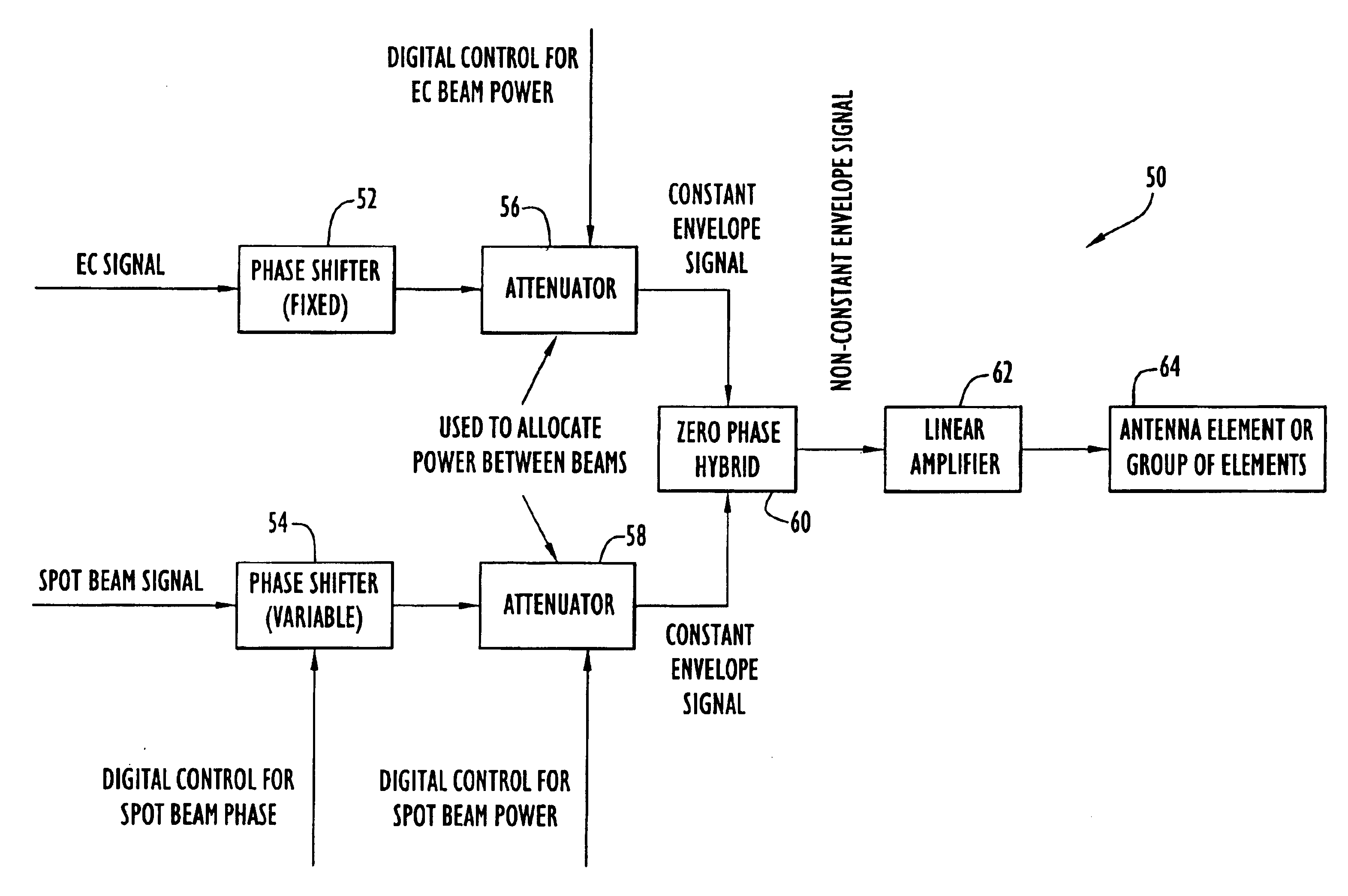
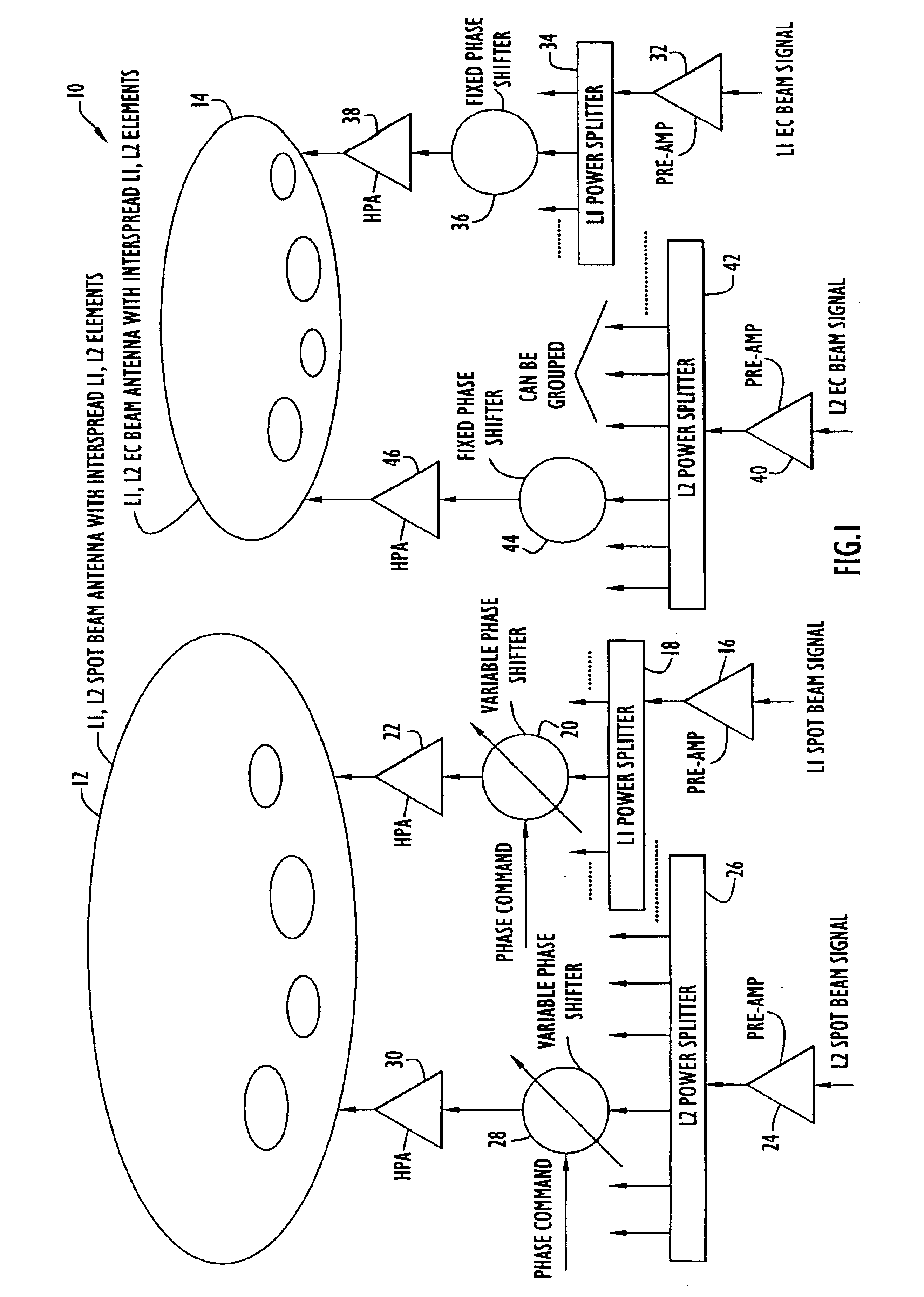
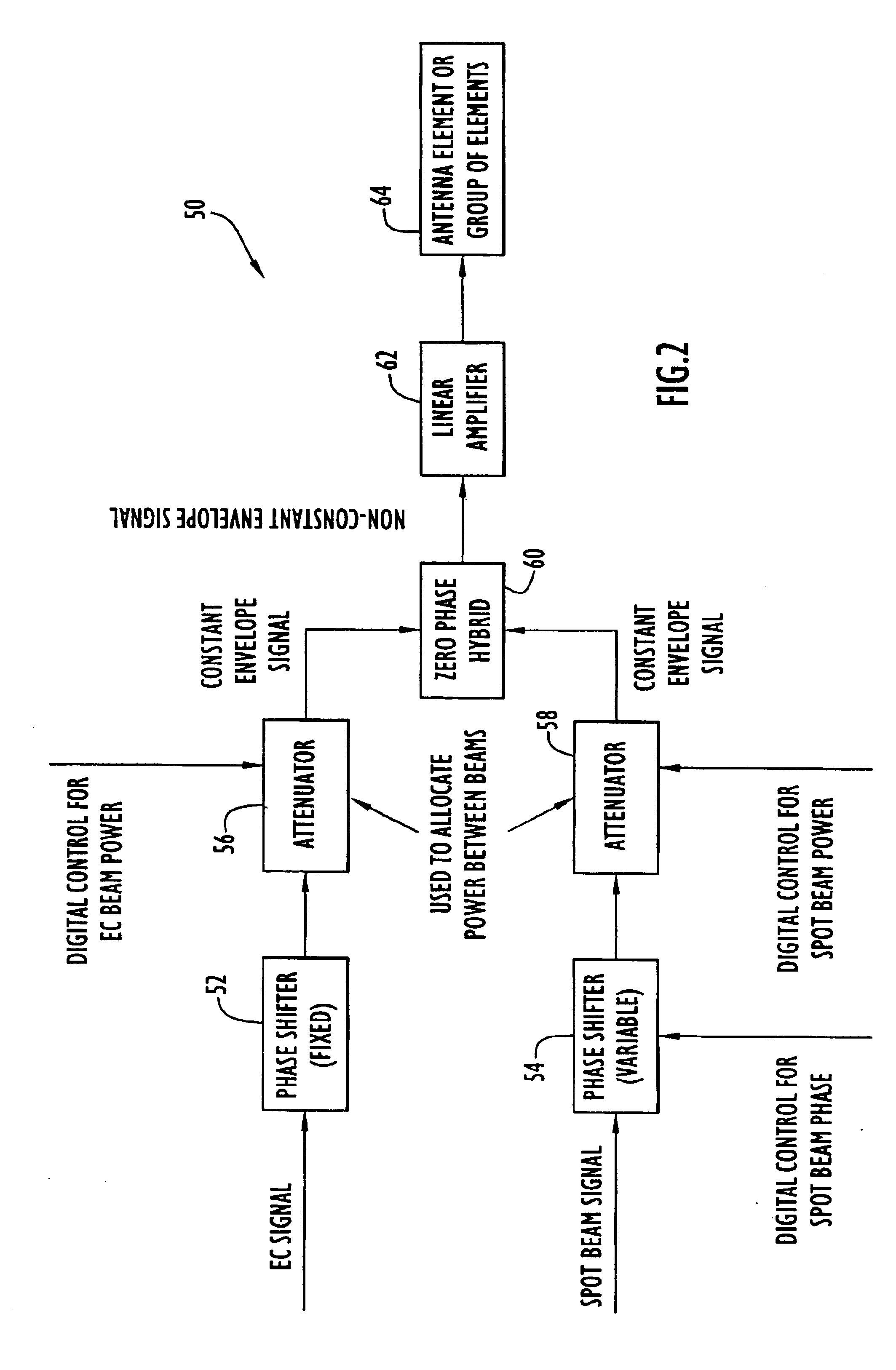
More specifically, for example, a method of transmitting two signals from a common antenna includes: generating a first signal for transmission via a first transmit beam; generating a second signal for transmission via a second transmit beam; forming a composite signal that includes the first and second signals, wherein the phase of the composite signal accounts for signal modulation and beam forming characteristics of the first and second signals; and transmitting the composite signal from the common antenna, thereby transmitting the first signal via the first transmit beam and transmitting the second signal via the second transmit beam. For example, the first transmit beam can be a GPS earth coverage beam and the second transmit beam can be a steerable GPS spot beam. This can be easily extended to include additional beams with additional signals.
With this embodiment, according to one approach, the digital composite signals are computed from a vector sum of the first and second digital signals. More specifically, for each antenna element, a composite phase is determined based on the phase and amplitude of the component signals, where the phase of each component signal is, in turn, determined from the instantaneous modulation phase and beam forming phase of the component signal for each antenna element. Advantageously, the composite signal can have a constant envelope, which permits the use of efficient, saturated high power amplifiers.
According to another approach, the digital composite signals are formed by interleaving the first and second digital signals in a time division manner. This approach avoids signal clipping that may occur with summing the signals. Distribution of power between the beams can be controlled by selecting the ratio of the time segments allocated to each of the signals in the interleave pattern.

Problems solved by technology

This greatly increases system cost, size, weight and power requirements over what would be required for a single phased array antenna and transmitter.
Also, the use of separate antennas and separate transmitters for the various beams (e.g., earth coverage and spot beams) limits the ability to rc-allocate power among the various beams.
However, a phased array configuration with different signals on each of the beams has not previously been implemented.
If non-constant envelope signals are applied to the HPAs, the use of highly efficient, saturated HPAs is precluded.
Linear methods that generate non-constant-envelope composite signals result in power-inefficient mechanizations, because the power amplifiers that are used for transmission of the composite signals must operate in the linear region.
Thus, linear combination techniques are maximally efficient in the sense that there is no actual signal power loss, but the overall efficiency of such techniques is compromised by the need to operate the amplifier at a significant power back-off to accommodate the instantaneous signal envelope fluctuations.
Non-linear multiplex methods that produce a constant-envelope composite signal permit a greater fraction of the available transmitter power to be used for communication, but at the expense of a multiplexing loss that may be characterized as an intermodulation product.
This multiplexing loss, however, is typically smaller than the power backoff it replaces, resulting in a favorable trade.
Therefore, constant-envelope signal structures are required if full-power, undistorted transmission is sought.

Method used


Image

  • Methods and apparatus for multi-beam, multi-signal transmission for active phased array antenna
  • Methods and apparatus for multi-beam, multi-signal transmission for active phased array antenna
  • Methods and apparatus for multi-beam, multi-signal transmission for active phased array antenna

Examples


Embodiment Construction

The system described herein provides a unique method for simultaneously transmitting multiple beams, each with its own signal component, from the same active phased array antenna. This configuration eliminates the need for separate antennas and transmitters for each of the required beams. The system is capable of forming multiple simultaneous beams, for example an earth coverage beam and multiple spot beams covering multiple theaters of operation, with the capability to re-allocate power among the various beams, which, in the context of satellite systems, can be performed on-orbit. The composite signal applied to each high-power amplifier (HPA) preferably, although not necessarily, has a constant amplitude envelope, which permits the use of saturated HPAs with their attendant power efficiency.

As used herein, the terms antenna beam(s), transmit beam(s) or simply “beam(s)”, including spot beams and earth-coverage beams, refer generally to radiated energy concentrated in a certain dire...


PUM


Abstract

A method and apparatus for simultaneously transmitting, at a common frequency, a plurality of signals on a plurality of beams from a phased array antenna involves forming composite signals that contain the plurality of signals. The composite signals correspond to respective antenna elements in the antenna array and include at least a first signal for transmission via a first transmit beam and a second signal for transmission via a second transmit beam. The phases of the composite signals are a function of signal modulations of the first and second signals and phases of the respective antenna elements required to form the first and second transmit beams. By digitally forming the composite signals, taking into account the modulation phase and beam-forming phase of each signal at each antenna element, hardware requirements are reduced and efficient, saturated amplifier can be employed.

Description

BACKGROUND OF THE INVENTION1. Field of the InventionThe present invention relates to methods and apparatus for generating multi-beam, multi-signal transmissions using an active phased array antenna.2. Description of the Related ArtThere are many communications, radar, and navigation applications that require multiple transmit beams from a common site, with different signals on the various beams. For example, the next generation of Global Positioning System (GPS) satellites will require the transmission of spot beams to direct higher power military signals to theaters of operation, along with broader earth coverage beams for conventional navigational users. Proposed solutions include the use of a separate gimbaled antenna to provide the spot beam, in addition to the existing earth coverage antenna. Alternative approaches using an active phased array antenna with an electronically steered beam to implement the spot beam have also been proposed.The use of a separate antenna (mechanical...

Claims


Application Information

Patent Timeline
Patent Type & Authority Patents(United States)
IPC IPC(8): H01Q1/28H01Q1/27H01Q3/34H01Q3/30H01Q21/06H01Q25/00H04B7/04H04B7/06
CPCH01Q1/288H01Q3/34H04B7/0617H01Q25/00H01Q25/002H01Q21/06
Inventor CANGIANI, GENE L.
Owner EXCELIS INC
Learn More