
Tools for securing connectors using explosive charges and methods for using the same

a technology of explosive charges and tools, which is applied in the direction of manufacturing tools, engine starters, explosion-based starters, etc., can solve the problems of difficult operation of tools, compromise the formation or integrity of connections, and pressurized gas may harm users

Inactive Publication Date: 2005-02-08
TYCO ELECTRONICS LOGISTICS AG (CH)
View PDF16 Cites 22 Cited by
  • Summary
  • Abstract
  • Description
  • Claims
  • Application Information

AI Technical Summary

Benefits of technology

The present invention provides a tool for securing a connector on a conductor using an explosive charge. The tool includes a first tool member, a second tool member movably mounted on the first tool member, a breech chamber defined in at least one of the first and second tool members, a breech opening defined in at least one of the first and second tool members, and a drive member. The tool is adapted to forcibly move the drive member responsive to an explosion of the explosive charge in the breech chamber. The second tool member is movable between a closed position, wherein the breech opening is closed, and an open position, wherein the breech opening is open to allow loading and unloading of the explosive charge into and from the breech chamber, by sliding the second tool member relative to the first tool member along a slide axis and additionally pivoting the second tool member relative to the first tool member about a pivot axis transverse to the slide axis. The technical effect of the invention is to provide a tool that allows for easy and safe securing of connectors on conductors using explosive charges.

Problems solved by technology

However, the amount of force should not be excessive as this may compromise the formation or integrity of the connection.
If not first controllably released, the pressurized gas may harm the user when the user attempts to open the tool body to remove the expended explosive charge cartridge.
However, such tools may be difficult to operate under some circumstances or may require substantial and frequent maintenance to ensure safe and effective operation.

Method used


Image

  • Tools for securing connectors using explosive charges and methods for using the same
  • Tools for securing connectors using explosive charges and methods for using the same
  • Tools for securing connectors using explosive charges and methods for using the same

Examples


Embodiment Construction

The present invention now will be described more fully hereinafter with reference to the accompanying drawings, in which preferred embodiments of the invention are shown. This invention may, however, be embodied in many different forms and should not be construed as limited to the embodiments set forth herein; rather, these embodiments are provided so that this disclosure will be thorough and complete, and will fully convey the scope of the invention to those skilled in the art. Like numbers refer to like elements throughout.

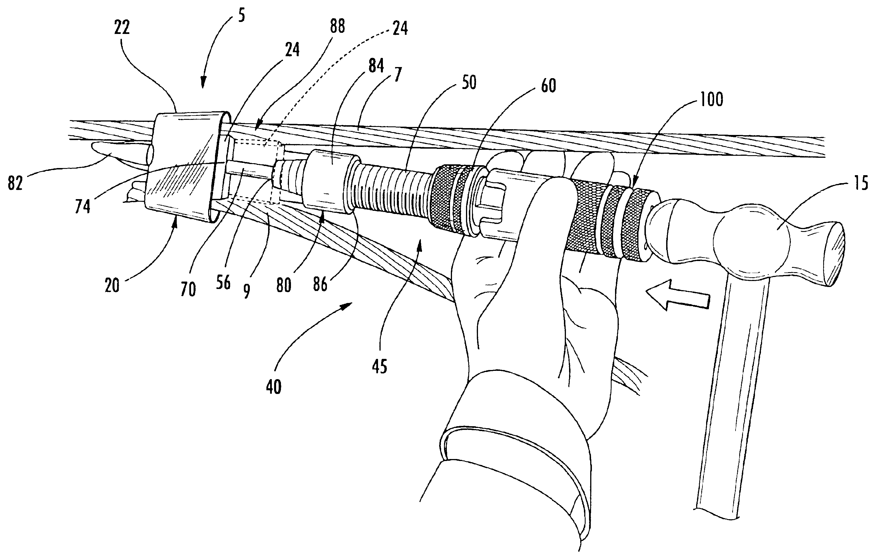
With reference to FIG. 1, a tool assembly 40 according to embodiments of the present invention is shown therein. The tool assembly 40 may be used to form a connection 5 as shown in FIG. 1, for example. The connection 5 includes a pair of conductors 7, 9 securely and electrically coupled by a connector 20. The connector 20 includes a C-shaped sleeve 22 and a wedge 24. Connectors of this type are well-known to those of skill in the art and will not be described in...


PUM


Abstract

A tool for securing a connector on a conductor using an explosive charge includes a first tool member and a second tool member movably mounted on the first tool member. A breech chamber is defined in at least one of the first and second tool members. The breech chamber is adapted to receive the explosive charge. A breech opening is defined in at least one of the first and second tool members and communicates with the breech chamber. A drive member is provided. The tool is adapted to forcibly move the drive member responsive to an explosion of the explosive charge in the breech chamber. The second tool member is movable between a closed position, wherein the breech opening is closed, and an open position, wherein the breech opening is open to allow loading and unloading of the explosive charge into and from the breech chamber, by sliding the second tool member relative to the first tool member along a slide axis and additionally pivoting the second tool member relative to the first tool member about a pivot axis transverse to the slide axis.

Description

FIELD OF THE INVENTIONThe present invention relates to tools and methods for using tools and, more particularly, to tools and methods for securing or terminating connectors.BACKGROUND OF THE INVENTIONElectrical cables often must be terminated or joined (spliced) in various environments, such as underground or overhead. Such cables may be, for example, high voltage electrical distribution or transmission lines. In order to form such connections, a connector may be employed. To install such connectors, it may be necessary to force two members into engagement, typically such that one or both of the members are deformed. Exemplary connectors include a C-shaped sleeve and wedge combination as disclosed in U.S. Pat. No. 4,722,189 to Center. In order to install such connectors, it is typically necessary to apply a relatively great force between the wedge and the sleeve. However, the amount of force should not be excessive as this may compromise the formation or integrity of the connection....

Claims


Application Information

Patent Timeline
Patent Type & Authority Patents(United States)
IPC IPC(8): B25B27/00H01R43/027H01R4/00H01R4/08H01R4/50
CPCB25B27/0085H01R43/0275H01R4/5083H01R4/08
Inventor GREGORY, OWENHERNANDEZ, WILLIE
Owner TYCO ELECTRONICS LOGISTICS AG (CH)
Learn More