
Irrigation control system

a control system and irrigation system technology, applied in the field of irrigation control system, can solve the problems of large amount of water wasted, over-irrigation, and water wastage, and achieve the effect of accurate management of irrigation of an area and minimising over-irrigation and hence water wastag

Inactive Publication Date: 2005-02-01
IRRIGATION CONTROL NETWORKS
View PDF4 Cites 57 Cited by
  • Summary
  • Abstract
  • Description
  • Claims
  • Application Information

AI Technical Summary

Benefits of technology

Using the system and method described above, it is possible to more accurately manage the irrigation of an area and minimise over irrigation and hence wastage of water.

Problems solved by technology

1. Relatively inexpensive controllers which are capable of executing an irrigation program. These controllers are not capable of changing the set irrigation program in any way to take account of differing water needs of plants occasioned by variations in meteorological conditions.
Such controllers will, if the irrigation program is not regularly modified inevitably waste considerable quantities of water, since it will be programmed to supply sufficient water to serve the needs of the plant being irrigated during periods when plant demand for water is high.
Thus when the same application of irrigation water continues during periods of low plant water requirement. wastage occurs.
The potential to save water by in effect harvesting rainfall by discontinuing irrigations until that rainfall finds its way into the root-zone and is transpired by the plants, is lost unless the controller can be manually de-activated.
When managing large numbers of such controllers, particularly over a wide area, it is generally not possible to manually de-activate them and re-activate them when irrigation should commence.
Additionally, such controllers are incapable of responding to occurrence of rain periods unless coupled to some specialist sensor designed for the purpose.
Whilst such sensors are known they tend to be either expensive (and consequently little used) or unreliable (and again little used).
2. More expensive controllers which can alter the frequency and amount of irrigation, either up or down, as time passes in an effort to match applications to plant requirements.
This type of controller is an improvement upon the first described type of controller, but is still arbitrary and inflexible as it relies on averages that must inevitably waste water when the predicted conditions do not occur.
Additionally, there can be no improvement in harvesting rainfall.
However, such controllers do not utilise localised rainfall measurement and consequently irrigation management depends upon rainfall information indicative of a wider area than the irrigation area.
Water wastage can result.
Further, these controllers must be part of a very wide network which means that over a wide area very considerable telephony or radio costs are necessarily involved.
In implementing certain forms of that invention, it has become apparent that where large numbers of sub-areas (such as parks, gardens and sports facilities) need to be managed by the system, special practical economic difficulties may arise.
However, weather stations are expensive and a very common characteristic of rainfall is that it can be extremely variable in amount and distribution even over a small area.
Thus to produce reliable data using such pulviometers is an expensive undertaking.

Method used


Image

  • Irrigation control system
  • Irrigation control system

Examples


Embodiment Construction

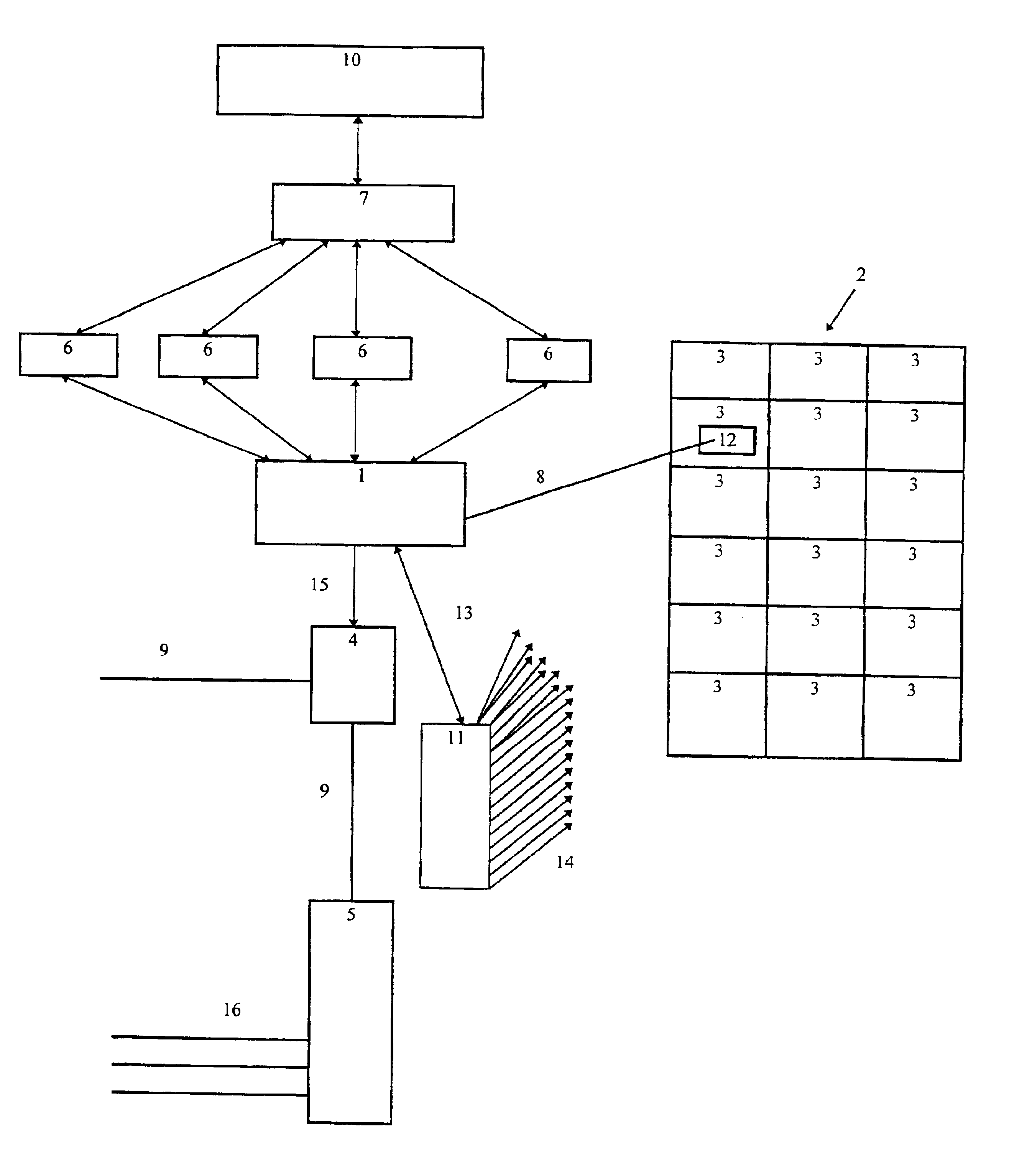
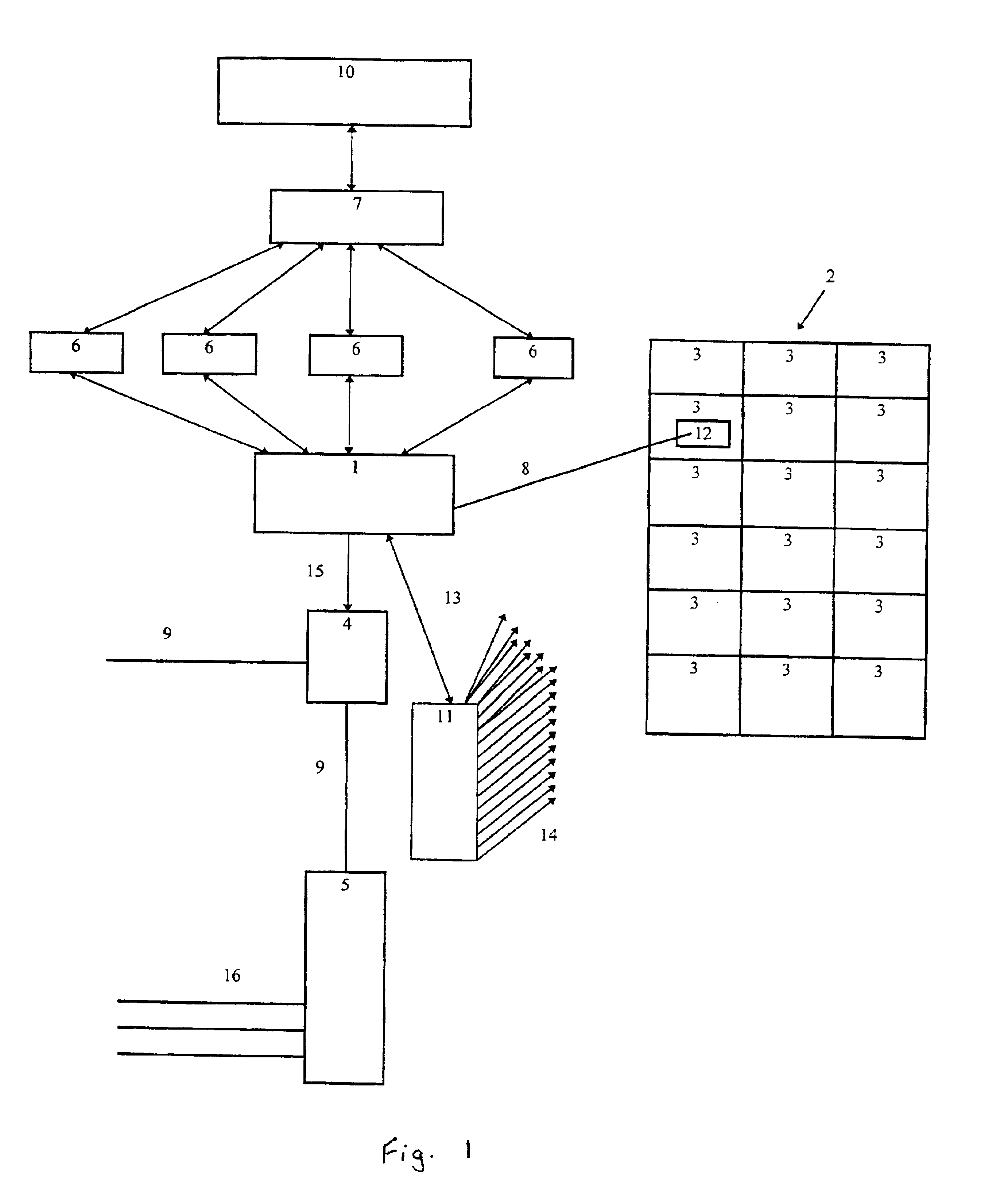
The invention will now be further explained and illustrated by reference to the following practical embodiment concerning steps (b) and (c) of the control system when dealing with the radar data.

As stated above, at present meteorological weather radars are commonly installed to cover the area of major cities. In the current example this area would be seen as the first area. The output of these radars is a stream of data organised in the following fashion:Radially—each degree of rotation from 000 through to 360 is reported separately.Longitudinally—for each degree of rotation, data is presented as a series of rain intensity figures, typically for each kilometer along each radii. For example 095 / 35 / 9 may mean that rain intensity of “9” is falling 35 kilometers from the radar transmitter on a bearing of 095 degrees from the transmitter.

This radar data may be processed as follows according to one aspect of the invention.

1. Firstly a “plane geometry” program is created and initialised. T...


PUM


Abstract

An irrigation control system for land comprising: (a) at least one meter to measure one or more wheather conditions in a first area; (b) at least one monitor to (i) examine rainfall data derived from a radar scanning at least the first area according to predetermined criteria and (ii) to extract data which is representative of the scanned rainfall in a sub-area of the first area; (c) a store to store the extracted data; and (d) a controller connected directly or indirectly to the meter and the monitor and to the store, to calculate a moisture content value for the sub-area and a predetermined moisture content value for the sub-area, and to regulate the irrigation in a sub-area.

Description

FIELD OF THE INVENTIONThe invention relates to an irrigation control system for a predetermined area. In particular, scheduling and management of urban irrigation of parks, gardens and sports facilities of a large city.BACKGROUND OF THE INVENTIONControllers to start and stop irrigation cycles without human intervention are well known. These controllers send an electric current (usually 24 volt alternating current in horticultural or agricultural use) to a remote solenoid valve, causing the valve to open. Valve closure is usually effected by discontinuing the supply of electric current to the solenoid of the valve whereupon the valve is caused to close.Most of these types of controllers are able to handle a number of valves, opening and closing them in a programmed succession for programmed times on programmed days of the week. This series of sequential valve opening and closing on specified days is generally referred to as “a program” or “an irrigation program”. Many of the known co...

Claims


Application Information

Patent Timeline
IPC IPC(8): A01G25/16
CPCA01G25/167Y10T137/1866Y02A40/22
Inventor TOWNSEND, JAMES DUNSTONE
Owner IRRIGATION CONTROL NETWORKS
Learn More