
Multi-phase and multi-module power system with a current share bus

a power system and current share technology, applied in the direction of electric variable regulation, process and machine control, instruments, etc., can solve the problems of limiting the achievable current equity, reducing overall system efficiency and reliability, and conventional solutions that do not provide a means of actively sharing current between several modules

Inactive Publication Date: 2005-02-01
TEXAS INSTR INC
View PDF3 Cites 53 Cited by
  • Summary
  • Abstract
  • Description
  • Claims
  • Application Information

AI Technical Summary

Benefits of technology

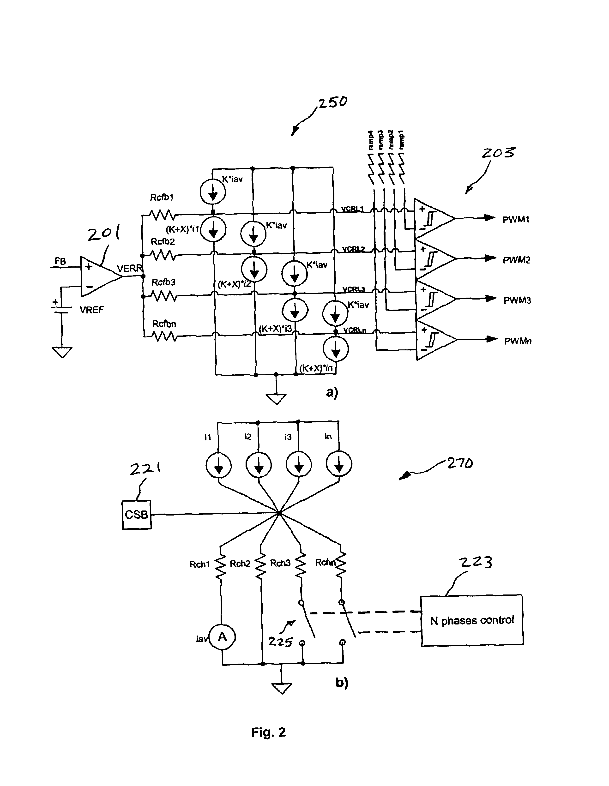
[0007]The present invention achieves technical advantages as an apparatus and system for current sharing in a multi-phased power system in which each phase has a power switch for selectively coupling a corresponding inductor to a source and a load, the multi-phased power system further including a sensor coupled with the inductors for sensing a channel current in each phase and providing a plurality of signals each representative of a corresponding channel current. Circuitry is included which is coupled with the sensor for receiving the channel signals for providing an average signal by summing the channel signals at a node which is coupled with a plurality of resistive elements corresponding to the number of phases of the multi-phased power syst...

Problems solved by technology

The increased current substantially increasing power dissipation in active and passive components effectively reducing overall system efficiency and reliability.
However, conventional current-mode systems operating over a wide range of input voltage have limited current feedback to avoid a sub-harmonic oscillation which tends to limit achievable current equity.
Also, conventional solutions do not provide a means to actively share the current between several modules.
In conventional voltage-mode systems, a high performance error amplifier with high bandwidth is typically required to boost the phase at frequencies higher than the converter's control loop crossover frequency which presents design challenges typically having extensive cost associated therewith.
Additionally, the voltage mode converters inherently have deprived response to the input voltage step which limits their applicability.

Method used


Image

  • Multi-phase and multi-module power system with a current share bus
  • Multi-phase and multi-module power system with a current share bus
  • Multi-phase and multi-module power system with a current share bus

Examples


Embodiment Construction

[0012]The numerous innovative teachings of the present application will be described with particular reference to the presently preferred exemplary embodiments. However, it should be understood that this class of embodiments provides only a few examples of the many advantageous uses and innovative teachings herein. In general, statements made in the specification of the present application do not necessarily delimit any of the various claimed inventions. Moreover, some statements may apply to some inventive features, but not to others. Throughout the drawings, it is noted that the same reference numerals or letters will be used to designate like or equivalent elements having the same function. Detailed descriptions of known functions and constructions unnecessarily obscuring the subject matter of the present invention have been omitted for clarity.

[0013]Conventional multi-phase power systems include a pulse width modulation (PWM) controller, power MOSFETs, and an LC output filter. T...


PUM


Abstract

A pulse width modulator (305) for driving a load in a multi-phased power system having circuitry (270) responsive to channel signals for providing an average signal by summing the channel signals at a node (221) which is coupled with a plurality of resistive elements, and having further circuitry for providing an error between said load and said reference potential, and having still further circuitry (250) for summing the channel signals, average signal, and error for providing a respective drive signal for each of the power switches, wherein the error signal and the average signal have complementary effects on a duty factor of the drive signals and the channel signal has an effect contrary to the error signal and the average signal. Further, a plurality of pulse width modulators (305) can be combined as a system (300) by connecting respective nodes (221) for providing current sharing between all phases.

Description

FIELD OF THE INVENTION[0002]The invention relates generally to integrated circuits and, more particularly, to a current-mode controlled multiphase power system.BACKGROUND OF THE INVENTION[0003]There is a strong trend in the field of low voltage DC / DC converters for computers and communication systems towards higher load currents. Increased load current requirements most often are addressed by the interleaved synchronous multi-phase converters. It is very important for reliability of synchronous multi-phase converters that all phases share the load equally. Inequality in phase currents results in increased current draw from the corresponding input rail above the current normally associated with load demand. The increased current substantially increasing power dissipation in active and passive components effectively reducing overall system efficiency and reliability. Also, it is often of major importance to some computer and communication systems to have the ability to scale the syste...

Claims


Application Information

Patent Timeline
IPC IPC(8): H02M3/158H02M3/04H02J1/10H02M3/155
CPCH02M3/1584
Inventor MURATOV, VLADIMIR ALEXANDERWIKTOR, STEFAN WLODZIMIERZ
Owner TEXAS INSTR INC
Learn More