Iron type golf club
a golf club and iron-type technology, applied in the field of golf clubs, can solve the problems of loss of feel and shot making performance, reduced feel from lack of mass or weight concentration behind the center of percussion, etc., and achieve the effects of improving shot making characteristics, thicker structure, and improved weight distribution
- Summary
- Abstract
- Description
- Claims
- Application Information
AI Technical Summary
Benefits of technology
Problems solved by technology
Method used
Image
Examples
first embodiment
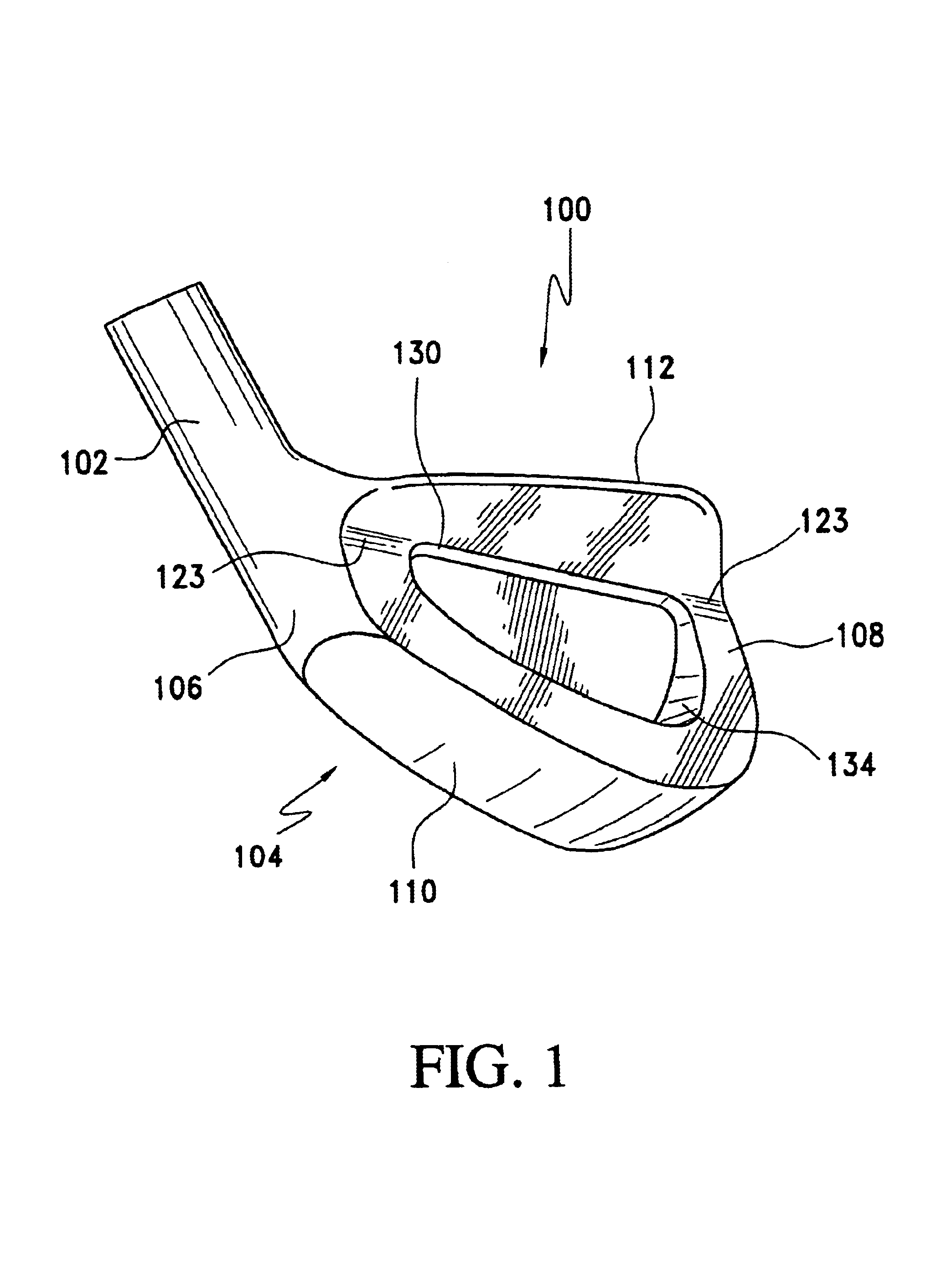
FIGS. 1, 2, 3 and 4 illustrate an iron type golf club head 100 made in accordance with the present invention. The club head 100 includes a hosel 102, and a club head body 104 including a heel 106, toe 108, bottom sole 110, top ridge 112 and a ball striking face 114 with a loft greater than 12 degrees. A leading edge 116 is defined by the intersection of the lower edge of the ball striking face 114 and the forward most progression of the bottom sole 110. These features are generally conventional in design. With most conventional iron type golf clubs the ball striking pattern on the club face usually varies with the caliber of golfer using the equipment.
As shown in FIG. 2, golfers with a high level of proficiency, such as professionals and low handicap amateurs typically will have a ball striking pattern close to the center of percussion illustrated by the area marked “A” on the drawing. Golfers with more moderate ability typically have a wider pattern identified by the letter “B” on ...
third embodiment
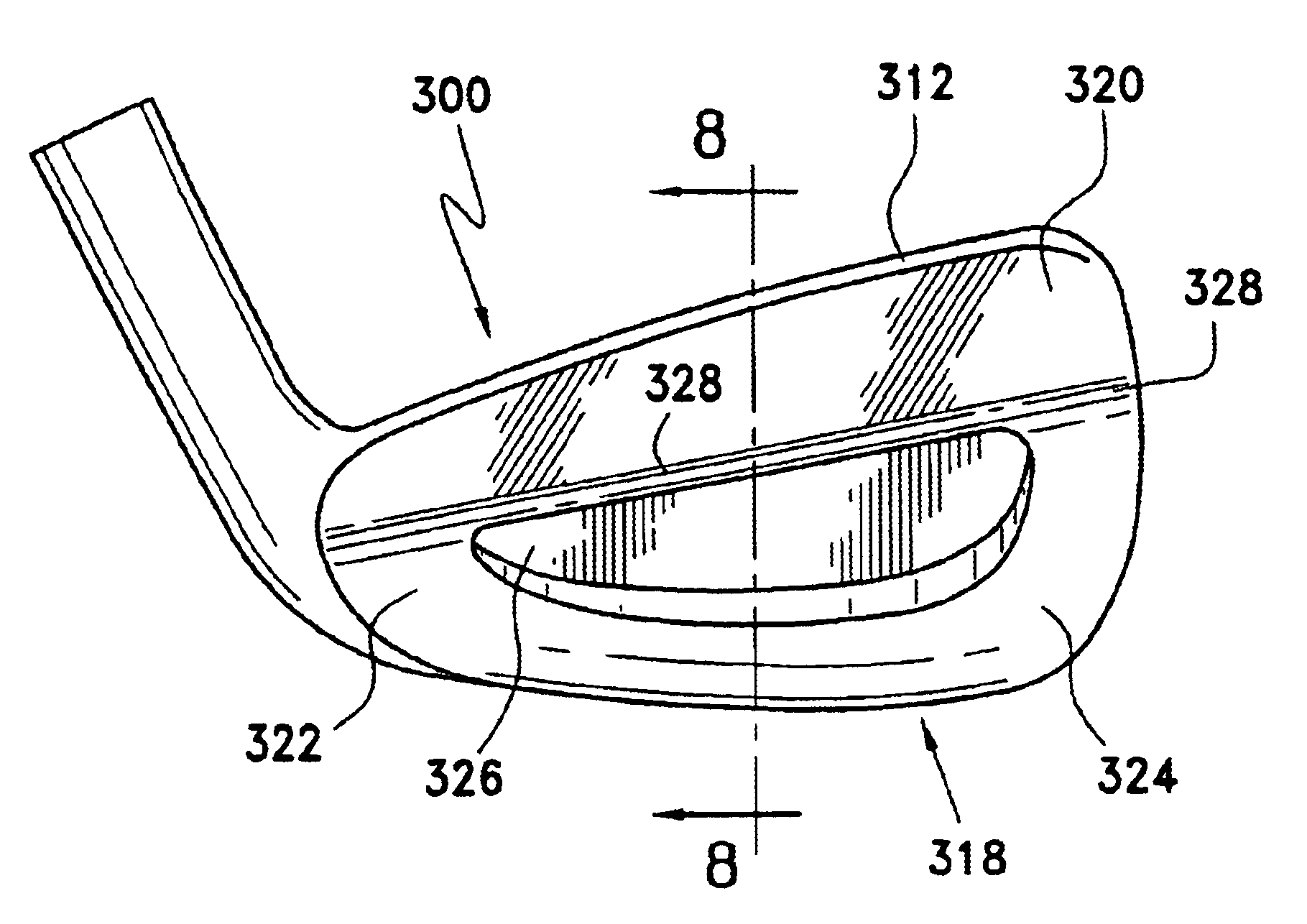
FIGS. 7 and 8 illustrate a golf club head 300 of the present invention, which includes a rear surface 318 including an upper portion 320 with a blade configuration below the top ridge 312 of the club head 300. A lower portion 322 of the rear surface 318 is formed with a thicker peripheral weight 324 and rear cavity 326. In this embodiment the rear cavity is located totally within the lower portion 322 and the interface 328 is a smooth, arcuate surface forming the transition area between the upper portion 320 and the lower portion 322.
FIGS. 9 and 10 illustrate a forth embodiment of a golf club head 400 of the present invention, which includes a rear surface 418 including an upper portion 420 with a blade configuration below the top ridge 412 of the club head 400. A lower portion 422 of the rear surface 418 is a generally muscle back type structure formed with a thicker peripheral weight 424 and rear cavity 426. In this embodiment the peripheral weight 424 extend outwardly from the re...
fifth embodiment
FIG. 11 illustrates a golf club head 500 of the present invention, which includes a rear surface 518 including an upper portion 520 with a blade configuration below the top ridge 512 of the club head 500. A lower portion 522 of the rear surface 518 is formed with a thicker peripheral weight 524 located toward the toe and a rear cavity 526, located toward the heel 506 of the club head 500 to accommodate golfers who tend to fade or slice the golf ball.
PUM
 Abstract
Description
Claims
Application Information
 - R&D
- Intellectual Property
- Life Sciences
- Materials
- Tech Scout
- Unparalleled Data Quality
- Higher Quality Content
- 60% Fewer Hallucinations
Browse by: Latest US Patents, China's latest patents, Technical Efficacy Thesaurus, Application Domain, Technology Topic, Popular Technical Reports.
© 2025 PatSnap. All rights reserved.Legal|Privacy policy|Modern Slavery Act Transparency Statement|Sitemap|About US| Contact US: help@patsnap.com


