
Repeatable runout determination within a rotating media storage device

a technology of rotating media storage and repeatable runout, which is applied in the direction of magnetic recording, data recording, instruments, etc., can solve the problems of track mis-registration (tmr), difficulty in servo control system achievement, and incorrect position information, so as to achieve the effect of quick determination of repeatable runout and repeatable runou

Inactive Publication Date: 2005-01-25
WESTERN DIGITAL TECH INC
View PDF5 Cites 116 Cited by
  • Summary
  • Abstract
  • Description
  • Claims
  • Application Information

AI Technical Summary

Benefits of technology

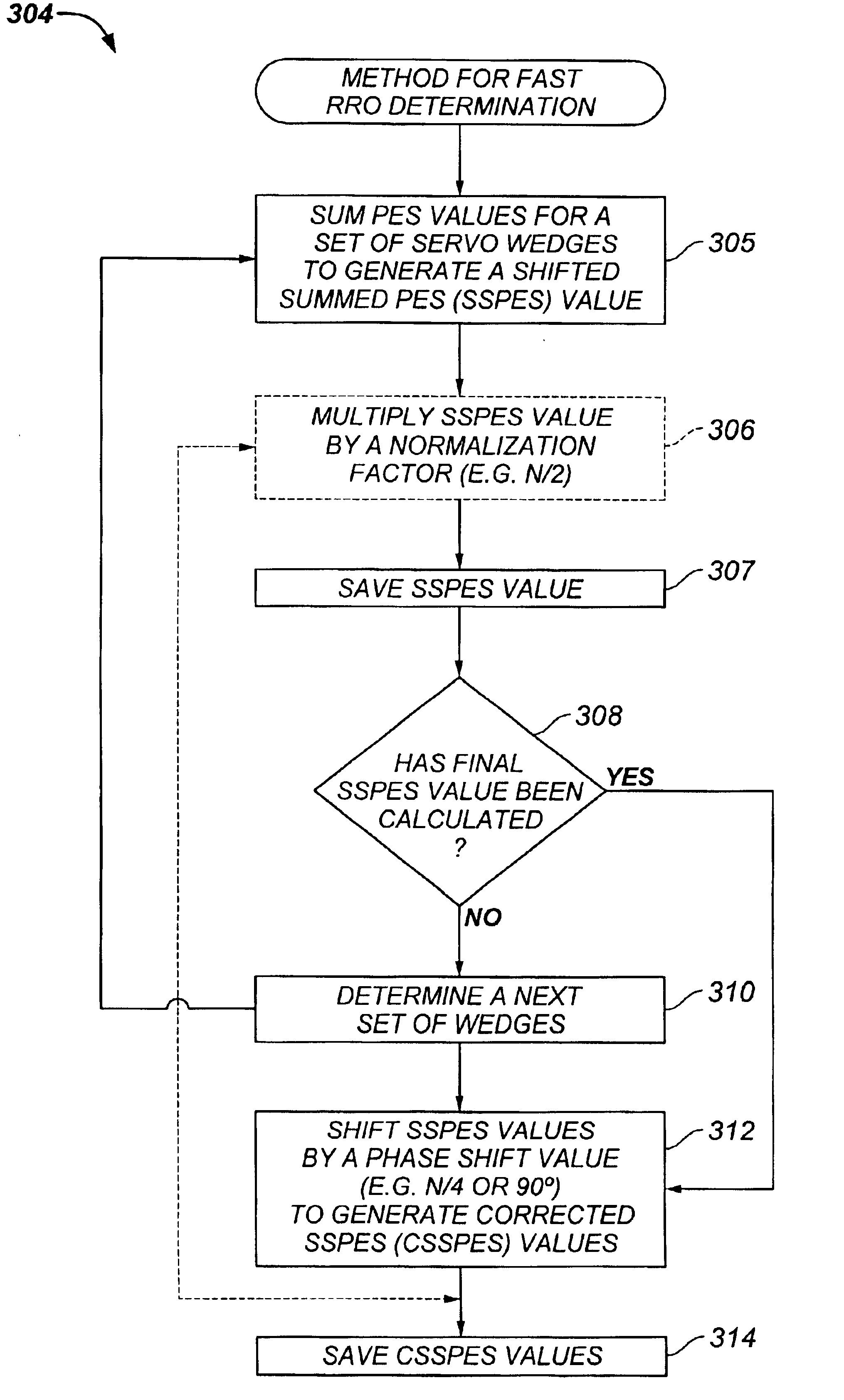
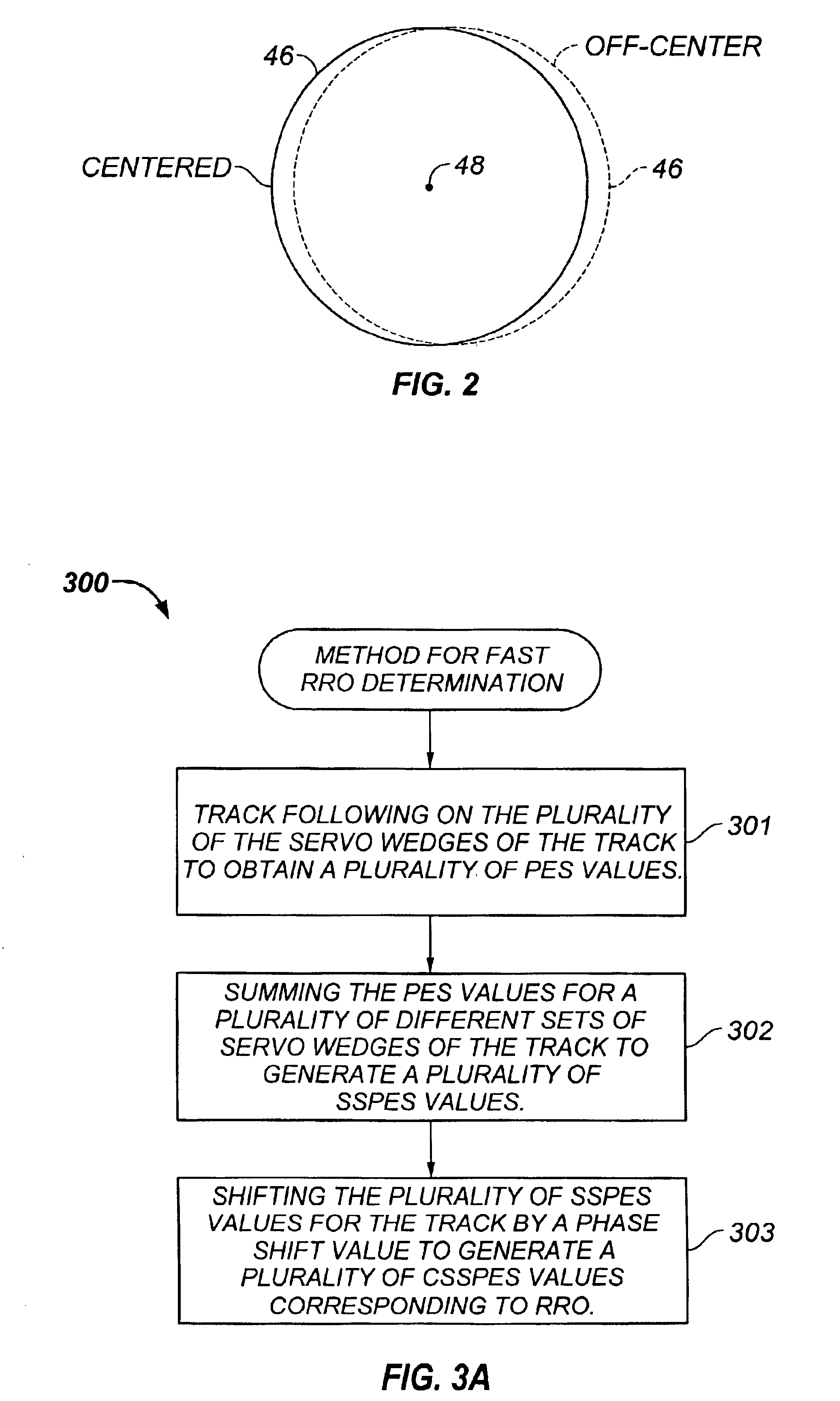
The present invention relates to quickly determining repeatable runout (RRO) within a rotating media storage device. In one aspect, the invention may be regarded as a method for repeatable runout (RRO) determination in a rotating media storage device (RMSD). The RMSD includes a disk having at least one track having a plurality of servo wedges, a moveable head, and a servo control loop for controlling the position of the moveable head to perform track following. The method comprises the steps of track following on the plurality of servo wedges of the track to obtain a plurality of position error signal (PES) values, summing the PES values for a plurality of different sets of servo wedges of the track to generate a plurality of shifted summed position error signal (SSPES) values, and shifting the plurality of SSPES values for the track by a phase shift value to generate a plurality of corrected shifted summed position error signal (CSSPES) values corresponding to the repeatable runout.
Preferably, a normalization factor is applied to one of the: generated SSPES values; or the generated CSSPES values. In one embodiment, the normalization factor is a constant divided by one half of the total number of servo wedges of the track. In this embodiment, each set of servo wedges includes a predetermined number of servo wedges that is one-half of the total number of servo wedges of the track. Moreover, in this embodiment, the phase shift value is one-quarter of the total number of servo wedges of the track. Also, the amplitude of one of the SSPES values or the CSSPES values may be modified based on an error rejection curve for the servo control loop.
In another aspect, the invention may be regarded as a RMSD having a disk including at least one track having a plurality of servo wedges, and a moveable head. Further, the RMSD includes a servo control loop for controlling the position of the moveable head to perform track following on a plurality of servo wedges of the track and to measure a plurality of position error signal (PES) values. Also, the RMSD includes a microprocessor under the control of a program to receive the plurality of PES values, sum the PES values for a plurality of different sets of servo wedges of the track to generate a plurality of shifted summed position error signal (SSPES) values, and shift the plurality of SSPES values for the track by a phase shift value to generate a plurality of corrected shifted summed position error signal (CSSPES) values. In still another aspect, the invention may be regarded as a computer system comprising a host computer and an RMSD, in which the RMSD further comprises a disk including at least one track having a plurality of servo wedges, a moveable head, and a servo control loop for controlling the position of the moveable head to perform track following on a plurality of servo wedges of a track and to measure a plurality of position error signal (PES) values. Also, the RMSD includes a microprocessor under the control of a program to receive the plurality of PES values, sum the PES values for, a plurality of different sets of servo wedges of the track to generate a plurality of shifted summed position error signal (SSPES) values, and shift the plurality of SSPES values for the track by a phase shift value to generate a plurality of corrected shifted summed position error signal (CSSPES) values.

Problems solved by technology

There are numerous outside influences, which make it difficult for the servo control system to achieve the desired transducer head position, but a particularly troublesome influence is known as “runout.”
RRO may also be caused by electromagnetic imperfections due to low quality servo bursts, even if they were mechanically recorded on the ideal circle.
This is true because the low quality bursts will yield incorrect position information.
Is Determining the RRO of a disk for use in track following is important because excessive RRO may cause track mis-registration (TMR) problems.

Method used


Image

  • Repeatable runout determination within a rotating media storage device
  • Repeatable runout determination within a rotating media storage device
  • Repeatable runout determination within a rotating media storage device

Examples


Embodiment Construction

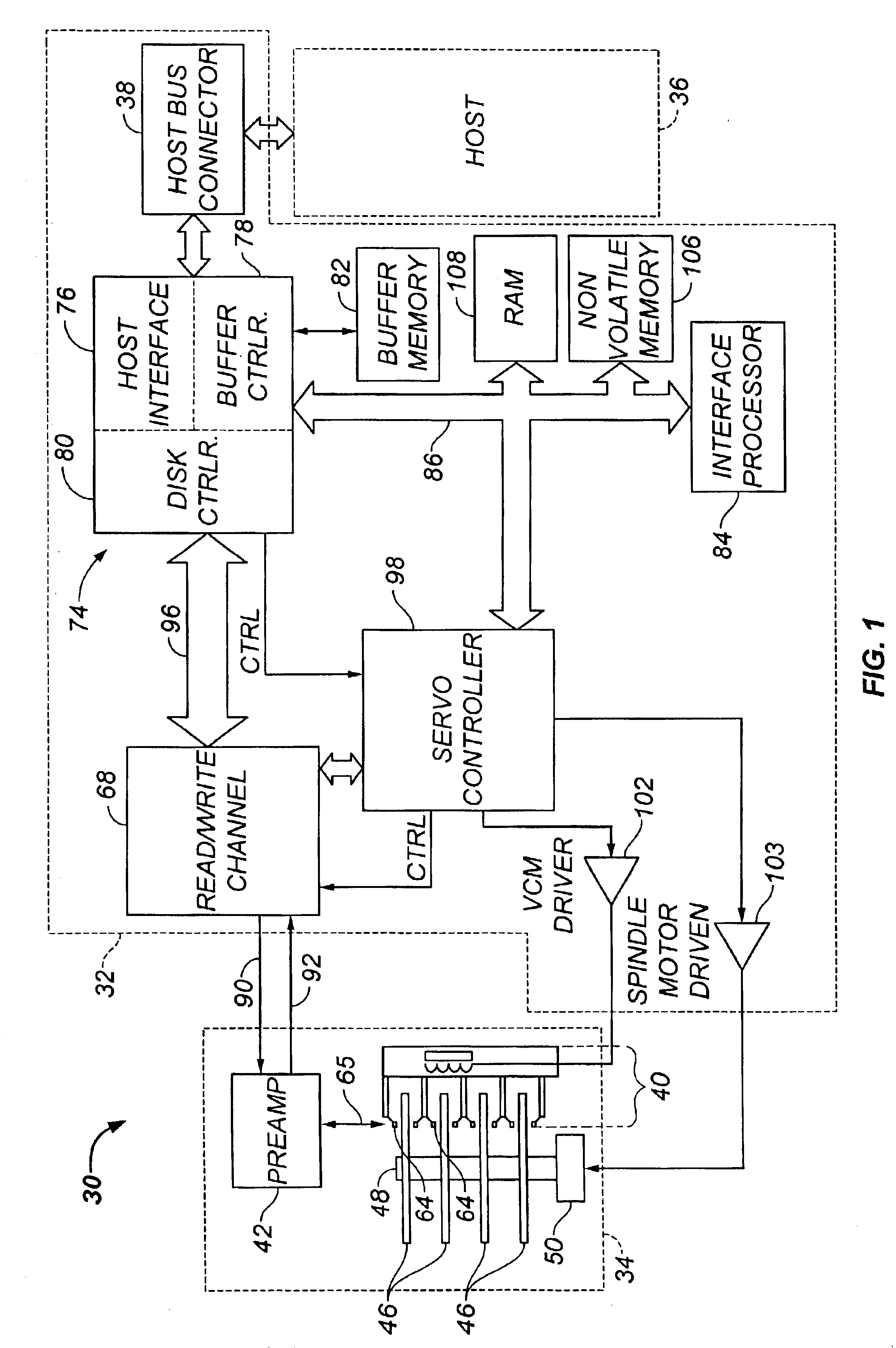
FIG. 1 shows a block diagram of a rotating media storage device (RMSD), such as disk drive 30, in which the invention may be practiced. Disk drive 30 is connected to a host computer 36 via host bus connector 38 for the transfer of commands, status and data. One suitable standard for such connection is the Advanced Technology Attachment (ATA) standard presently favored for desktop personal computers. Disk drive 30 comprises a Head / Disk Assembly, HDA 34, and a controller printed circuit board assembly, PCBA 32.

HDA 34 comprises: one or more disks 46 for data storage; a spindle motor 50 for rapidly spinning each disk 46 (four shown) on a spindle 48; and an actuator assembly 40 for swinging a plurality of moveable transducer heads 64 in unison over each disk 46. The moveable transducer heads 64 are connected to a preamplifier 42 via a cable assembly 65 for reading and writing data on disks 46. Preamplifier 42 is connected to channel circuitry in controller PCBA 32 via read 11 data line 9...


PUM

PropertyMeasurementUnit
phase shiftaaaaaaaaaa
frequencyaaaaaaaaaa
specific frequencyaaaaaaaaaa

Abstract

A rotating media storage device (RMSD) includes a disk having at least one track with a plurality of servo wedges, a moveable head, and a microprocessor. The microprocessor receives a plurality of position error signal (PES) values during track following and sums PES values for a plurality of different sets of servo wedges of the track to generate a plurality of shifted summed position error signal (SSPES) values. The microprocessor shifts the plurality of generated SSPES values by a phase shift value to generate a plurality of corrected shifted summed position error signal (CSSPES) values, which correspond to the repeatable runout (RRO) of the disk.

Description

BACKGROUND OF THE INVENTION1. Field of the InventionThe present invention relates to rotating media storage devices. More particularly, the present invention relates to an apparatus and method for repeatable runout (RRO) determination within a rotating media storage device.2. Description of the Prior Art and Related InformationA conventional disk drive has a head disk assembly (“HDA”) including at least one magnetic disk (“disk”), a spindle motor for rapidly rotating the disk, and a head stack assembly (“HSA”) that includes a head gimbal assembly (HGA) with a transducer head for reading and writing data. The HSA forms part of a servo control system that positions the transducer head over a particular track on the disk to read or write information from that track.Each surface of each disk conventionally contains a plurality of concentric data tracks angularly divided into a plurality of data sectors. In addition, special servo information is provided on each disk or on another disk t...

Claims


Application Information

Patent Timeline
Patent Type & Authority Patents(United States)
IPC IPC(8): G11B5/596
CPCG11B5/59627
Inventor CODILIAN, RAFFI
Owner WESTERN DIGITAL TECH INC
Learn More