
Video inspection device

a video inspection and video technology, applied in the field of electronic inspection equipment, can solve the problems of inability to visualize a particular part, difficulty in diagnosing and difficulty in carrying out diagnostic, maintenance and repair operations

Inactive Publication Date: 2005-01-25
SNAP ON INC
View PDF14 Cites 60 Cited by
  • Summary
  • Abstract
  • Description
  • Claims
  • Application Information

AI Technical Summary

Benefits of technology

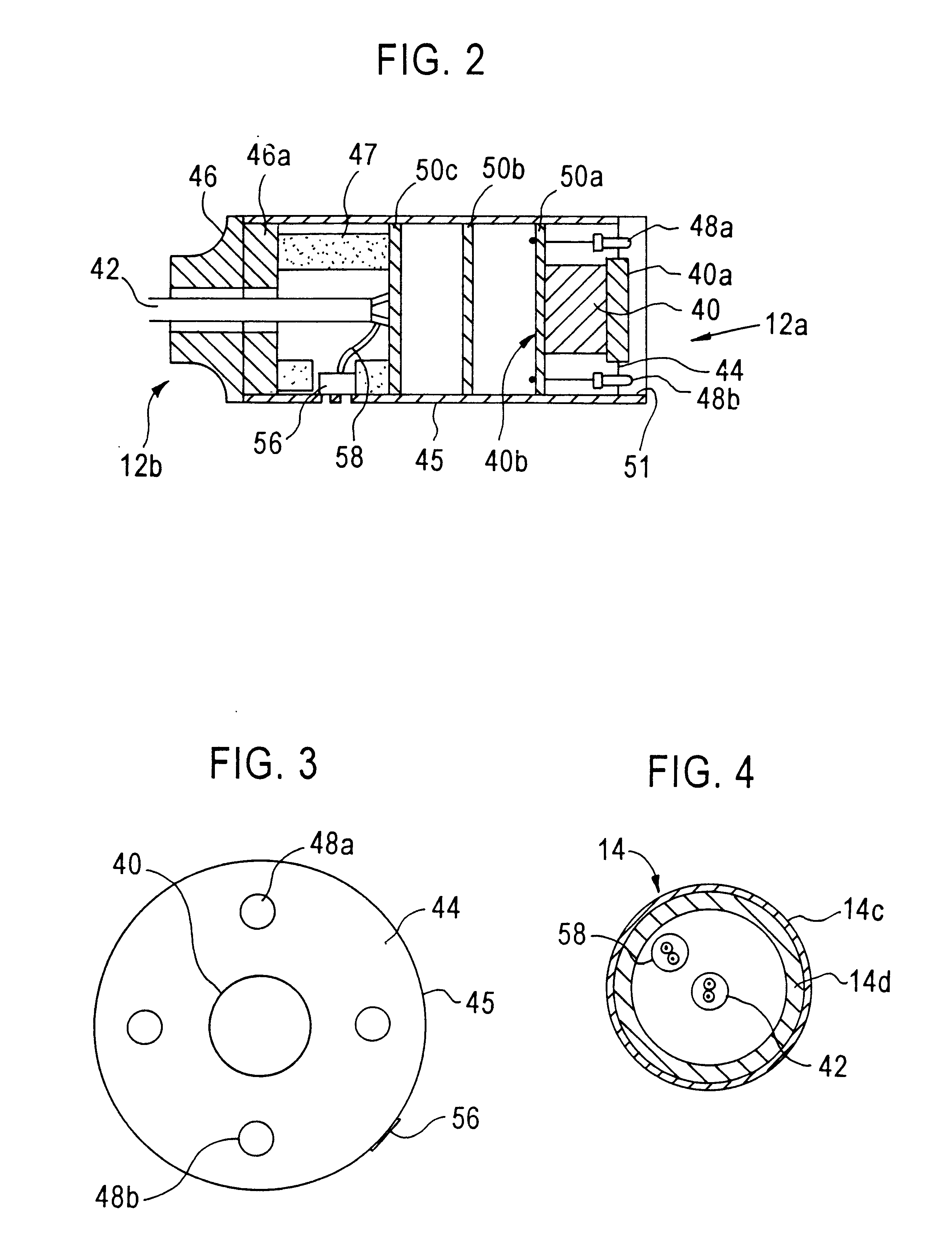
In another feature, the shaft comprises a material that withstands an ambient temperature of an engine compartment of a motor vehicle. Another feature is that the apparatus may further comprise an audio transducer mounted near the sensor that receives sounds produced by the object and that is coupled through the shaft to an audio output connector proximate to the housing. A related feature is that the audio transducer comprises one or more microphones. Still another feature is that the audio transducer comprises one or more microphones mounted in a sensor housing at the distal end of the shaft.
According to another feature, the inspection apparatus further comprises a sensor connector in the housing and coupled to the sensor to communicate a first signal representing sensed radiation to one or more external devices, and an audio output connector in the housing and coupled to the microphones to communicate a second signal representing audio sensed therefrom to the external devices. Still another feature is that the sensor and the radiation source are mounted in the sensor housing. Yet another feature is that the radiation source comprises one or more light-emitting diodes mounted around a perimeter of the sensor.

Problems solved by technology

Mechanical devices normally require periodic maintenance and repair.
For complex mechanical devices such as internal combustion engines, carrying out diagnostic, maintenance and repair operations may be difficult because of the close proximity of parts and tight clearances between parts.
The technician may be unable to visualize a particular part because it is adjacent to, inside of, or obscured by another part or assembly.
Under these circumstances, the technician may be forced to disassemble the mechanical device merely to visualize a possible problem source.
If the problem is not located at the suspected source, the technician must re-assemble the device, wasting valuable time.
In the field of motor vehicle repair, for example, diagnosing and repairing electrical problems associated with dashboard electronics may require the technician to disassemble the dashboard and its sub-assemblies—a time-consuming, complex task—merely to visualize parts and assess possible problems.
A further problem is inadequate illumination.
A technician may be able to locate a particular part, but may be unable to visualize it because of shadows cast on it or lack of direct or indirect illumination.
Some mechanical maintenance and repair operations also require the technician to inspect or handle a mechanical device under dangerous conditions.
A technician who places the hands adjacent a hot, running engine risks a variety of injuries.
This is undesirable because the context in which the failure occurred may be pertinent to failure analysis, but cannot be captured in an image once the parts or assemblies are taken apart.
Available bore scopes use fiber optic detectors to produce an image and typically have very limited image resolution.
Therefore, bore scopes are not suitable for inspection of wiring harnesses, and cables that use color-coding.
Thus, the usefulness of bore scopes is quite limited, and they cannot be used for inspection and visualization of large parts or assemblies.

Method used


Image

  • Video inspection device
  • Video inspection device
  • Video inspection device

Examples


Embodiment Construction

An inspection apparatus is described. In the following description, for the purposes of explanation, numerous specific details are set forth in order to provide a thorough understanding of the present invention. It will be apparent, however, to one skilled in the art that the present invention may be practiced without these specific details. In other instances, well-known structures and devices are shown in block diagram form in order to avoid unnecessarily obscuring the present invention.

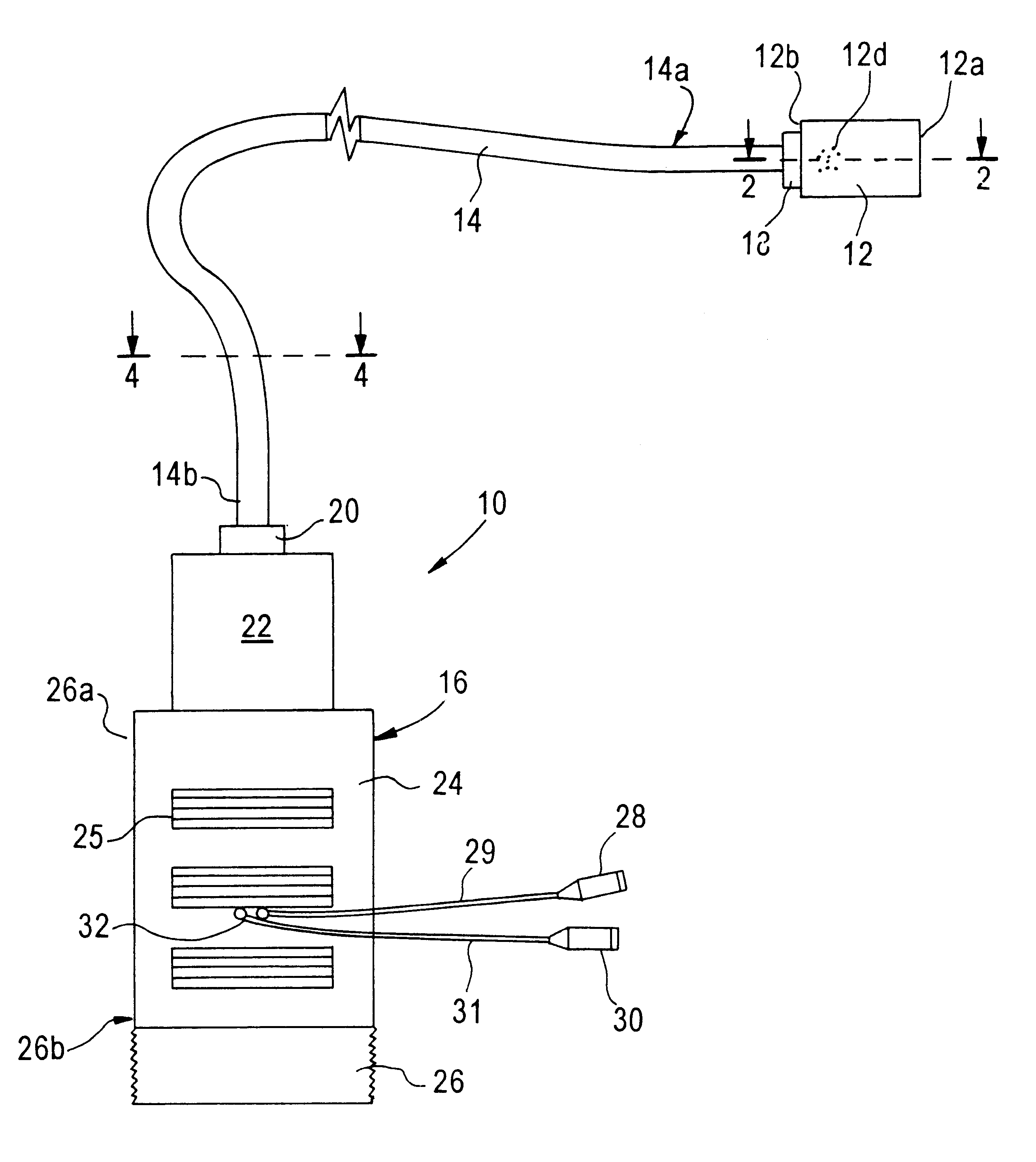
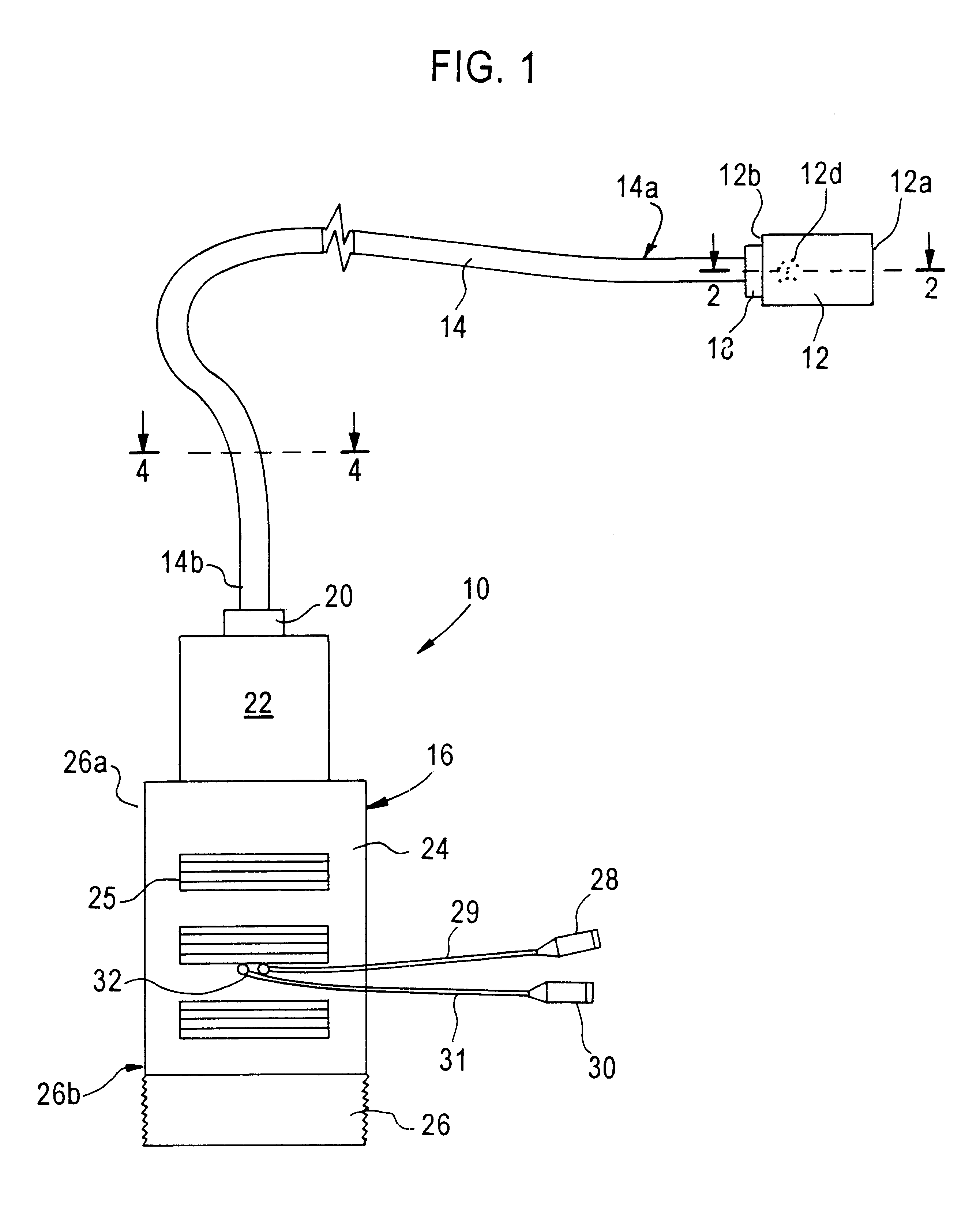
FIG. 1 is a part side elevation, part schematic view of an inspection apparatus 10, according to an exemplary embodiment. Inspection apparatus 10 generally comprises a sensor housing 12, shaft 14, and power housing 16.

Sensor housing 12 is cylindrical and has an open end 12a through which a sensor therein may receive electromagnetic radiation reflected from or emitted by an object that is inspected using the apparatus 10. Sensor housing 12 also has a closed end 12b that is coupled to a distal end 14...


PUM


Abstract

An inspection apparatus adapted for use in motor vehicle maintenance and repair is disclosed. A sensor, such as a video camera, is coupled by an elongated, flexible shaft to a self-contained, handheld power source. A source of illumination is mounted near the sensor and directs light onto an object that is viewed by the sensor. Input power to the sensor and the illumination source, and an output signal from the sensor, are coupled through the shaft, which will maintain any desired flexed position. Optionally, one or more microphones are mounted near the sensor to receive sounds produced by the object. Connectors extend from a housing of the power source so that the sensor output signal and an output from the microphones may be coupled to an external device. A removable clamp may be affixed to the apparatus so that the apparatus can be temporarily attached to a motor vehicle. As a result, a technician may easily visualize parts of the motor vehicle safely, clearly, and without disassembling the parts.

Description

FIELD OF THE INVENTIONThe present invention relates to electronic inspection equipment. The invention relates more specifically to video inspection equipment useful in diagnostic and repair applications.DESCRIPTION OF RELATED ARTMechanical devices normally require periodic maintenance and repair. Some maintenance and repair operations involve a diagnostic phase in which a technician inspects or observes the device to determine what work is required or what defects are present. For complex mechanical devices such as internal combustion engines, carrying out diagnostic, maintenance and repair operations may be difficult because of the close proximity of parts and tight clearances between parts. The technician may be unable to visualize a particular part because it is adjacent to, inside of, or obscured by another part or assembly.Under these circumstances, the technician may be forced to disassemble the mechanical device merely to visualize a possible problem source. If the problem is...

Claims


Application Information

Patent Timeline
Patent Type & Authority Patents(United States)
IPC IPC(8): H04N5/225H04N7/18
CPCH04N7/18H04N5/2256H04N23/56
Inventor HANSEN, RICHARD W.ELMENDORF, PATRICKSHAPIRO, BRUCEHENNEN, VIRGIL CHIP
Owner SNAP ON INC
Learn More