Method and handheld device for printing

Inactive Publication Date: 2005-01-25
PRINT DREAMS EURO
View PDF34 Cites 48 Cited by
  • Summary
  • Abstract
  • Description
  • Claims
  • Application Information

AI Technical Summary

Benefits of technology

A main object of the invention is to provide a method and device for performing an accurate and high-quality printout with a handheld printing device with no mechanisms for automatic feed of a printing paper or automatic steering of a print head.
The invention relates to a method and device for printing, comprising a graphical screen through which a non-automatic printing process can be supervised, in particular a method where the user steers the entire device by hand over the printing surface. The automatic steering of a print head has thus been replaced by manual movements. This enables a faster printout, especially for printouts having text or images spread out over the printout surface with much empty space in between. The print head can be moved by hand directly to the area where the text or image is to be printed.
By designing a “virtual” window in the screen, where a dynamic picture corresponding to the actual printout is re-created, a feeling of seeing right through the screen and directly onto the printing paper is accomplished. In this way, the printout process can be supervised effectively in real-time.
The other object of the invention, i.e. to enable a convenient start of the whole printout with great precision, is achieved by showing an easily recognisable part of the picture, e.g. the upper left-hand corner of the printout, on the screen. The device can then be positioned exactly where the printout is to be started. Then the printout may be started by means of a push button.
As a supplement to the “virtual” window on the screen, a group of 4-8 arrows may be shown beside it. These arrows are intended to guide the user where to lead the printing device for the printout to be accomplished faster.

Problems solved by technology

This is a drawback, since the print head has to sweep over the entire printout surface even if it is to be active only in relatively small areas, such as for example, the lower right-hand corner of the printout.
A further drawback with conventional printers is their great size, which means that they are more or less stationary.

Method used


Image

  • Method and handheld device for printing
  • Method and handheld device for printing
  • Method and handheld device for printing

Examples


Embodiment Construction

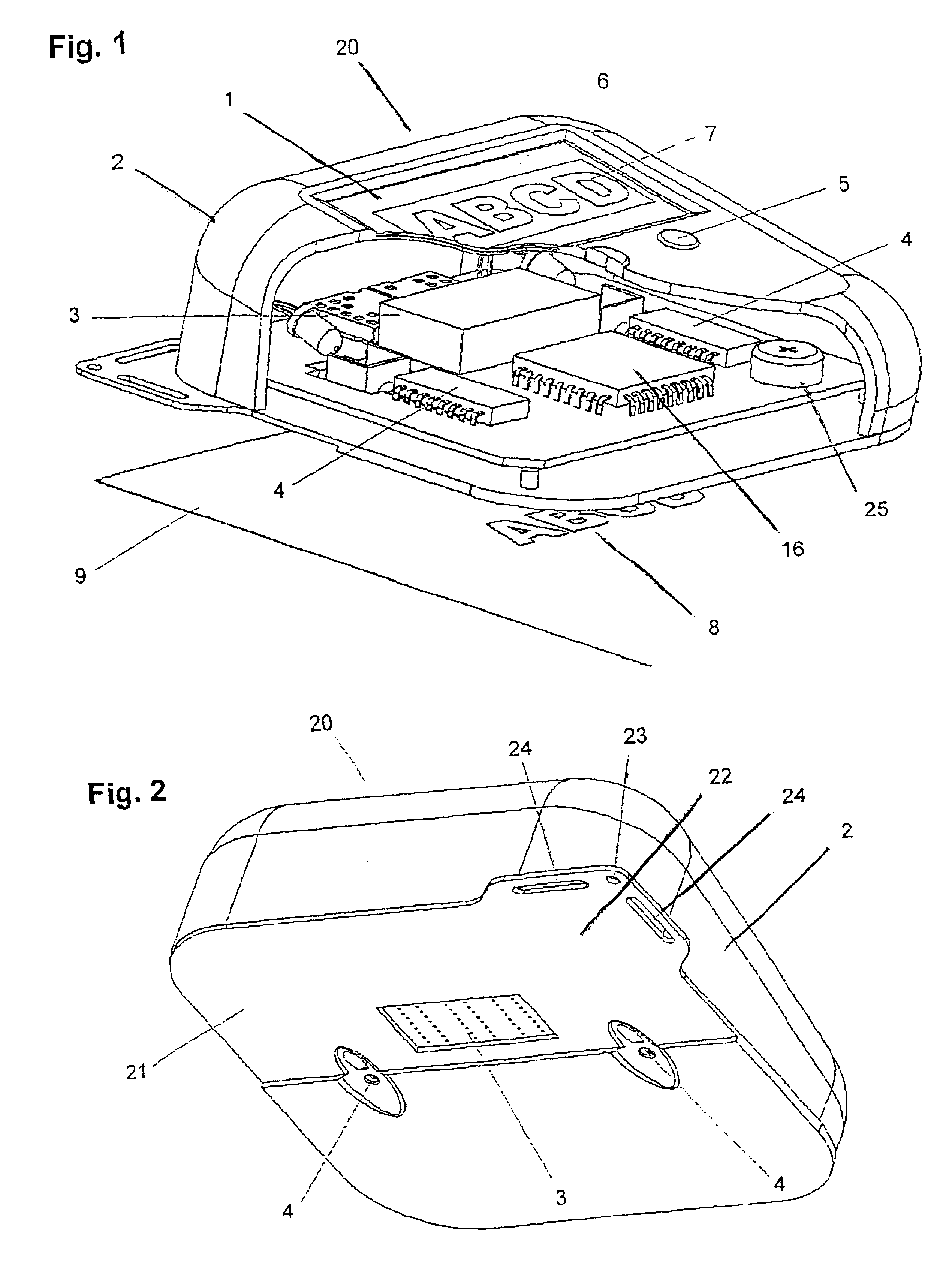
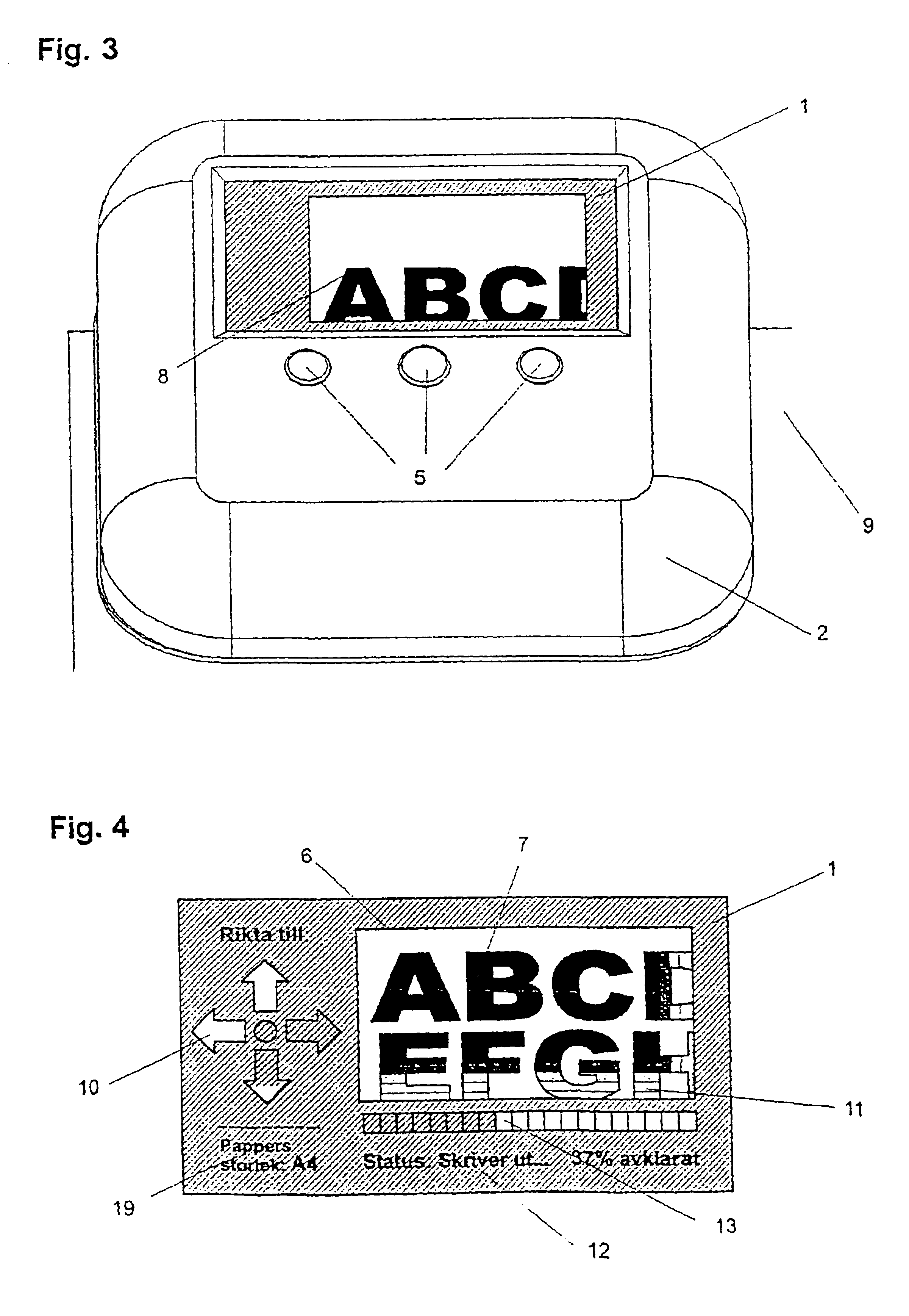
In FIG. 1, there is shown a screen 1 built into a handheld printing device 20 comprising a print head 3 co-operating with one or more positioning sensors 4, a micro controller circuit 16 and one or more command buttons 5. The print head may be an ordinary ink-jet printer, e.g. a piezo jet printer Model Xaar Jet128, available from XaarJet. Alternatively, a bubble jet print head could be used. The screen 1 is preferably an OLED (Organic Light Emitting Diods), available from for example RITEK Display Technology, but could be an ordinary LCD (Liquid Crystal Display) or a TFT (Thin Film Technology). OLEDs are preferred since they have fast response times.

The printing device according to the present invention also includes a housing 2 (preferably made of a plastic material, but could of course be of any other suitable material), mounted on a bottom plate 21. The bottom plate has openings for the print head 3 and one or more sensors 4. The bottom plate 21 is not of uniform thickness, but i...


PUM


Abstract

A handheld printing device and method for printing are disclosed. The handheld device comprises a print head, a graphical screen and at least one positioning sensor that co-operates with a micro controller circuit. The print head can be moved by hand directly to the area where the text or image is to be printed, and can be automatically steered to enable a faster printout, especially for printouts having text or images spread out over the printout surface with empty space in between. The manual movement of the print head is facilitated by the graphical screen of the device showing at each moment a portion of the picture corresponding in position to the printout in progress.

Description

FIELD OF THE INVENTIONThe invention relates to a handheld device for printing and a method of printing with a handheld device.BACKGROUND OF THE INVENTIONConventional printers of today operate with automatic feed, where the print head moves over the printout surface in a predetermined pattern. This is a drawback, since the print head has to sweep over the entire printout surface even if it is to be active only in relatively small areas, such as for example, the lower right-hand corner of the printout.A further drawback with conventional printers is their great size, which means that they are more or less stationary.OBJECTS OF THE INVENTIONA main object of the invention is to provide a method and device for performing an accurate and high-quality printout with a handheld printing device with no mechanisms for automatic feed of a printing paper or automatic steering of a print head.Another object of the invention is to enable a convenient start of the whole printout with great precisio...

Claims


Application Information

Patent Timeline
IPC IPC(8): B41J3/36B41J3/28B41J3/407B41J29/42
CPCB41J3/36
Inventor WALLING, ALEX
Owner PRINT DREAMS EURO
Why Eureka
Try Eureka