
Tourbillion

Inactive Publication Date: 2005-01-25
LANGE UHREN
View PDF8 Cites 22 Cited by
  • Summary
  • Abstract
  • Description
  • Claims
  • Application Information

AI Technical Summary

Benefits of technology

The object of the invention is thus to provide a tourbillon of the type mentioned in the introduction which easily allows the pivoting movement of the balance wheel to be blocked when a setting device of the timepiece is actuated.
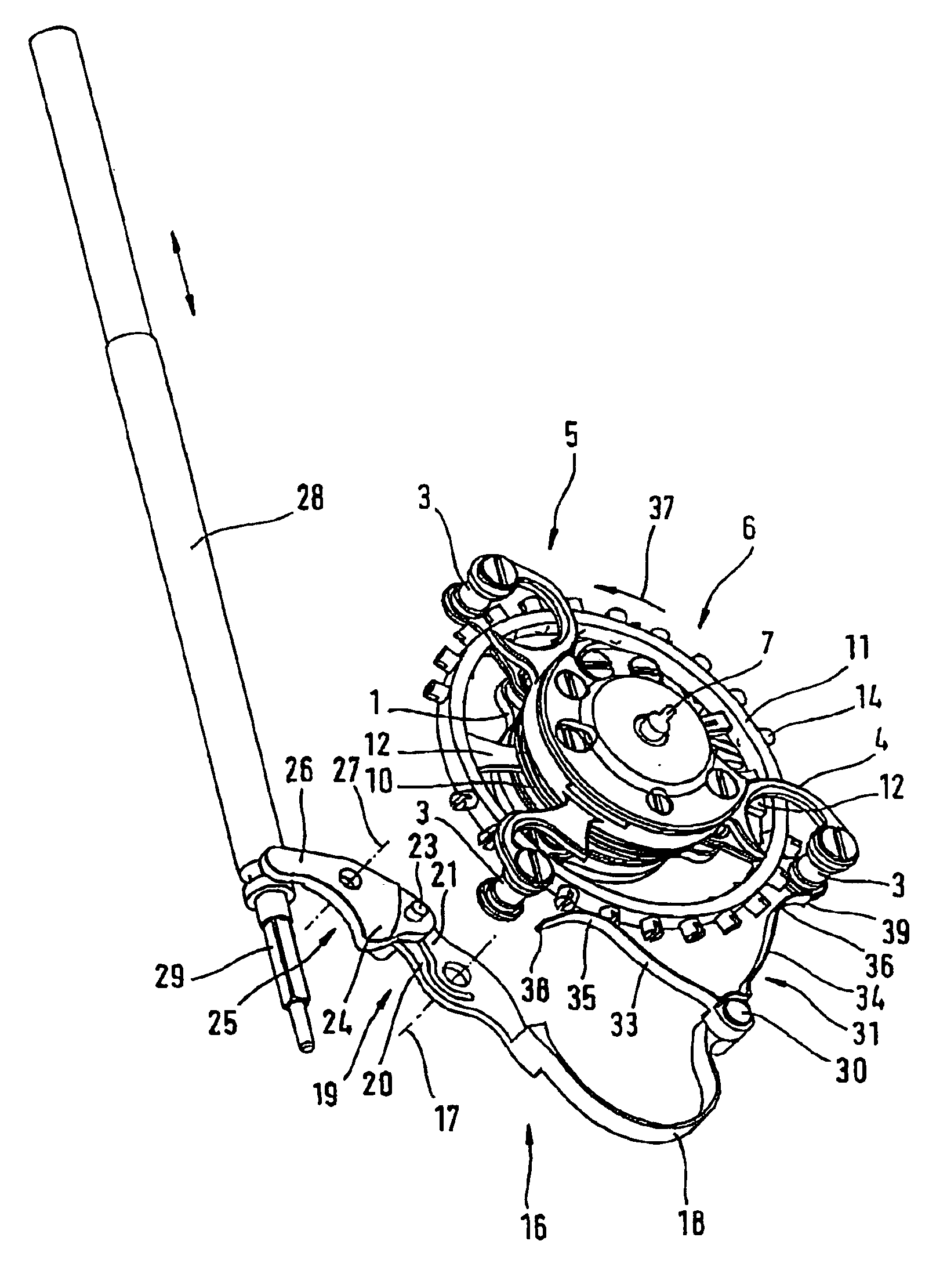
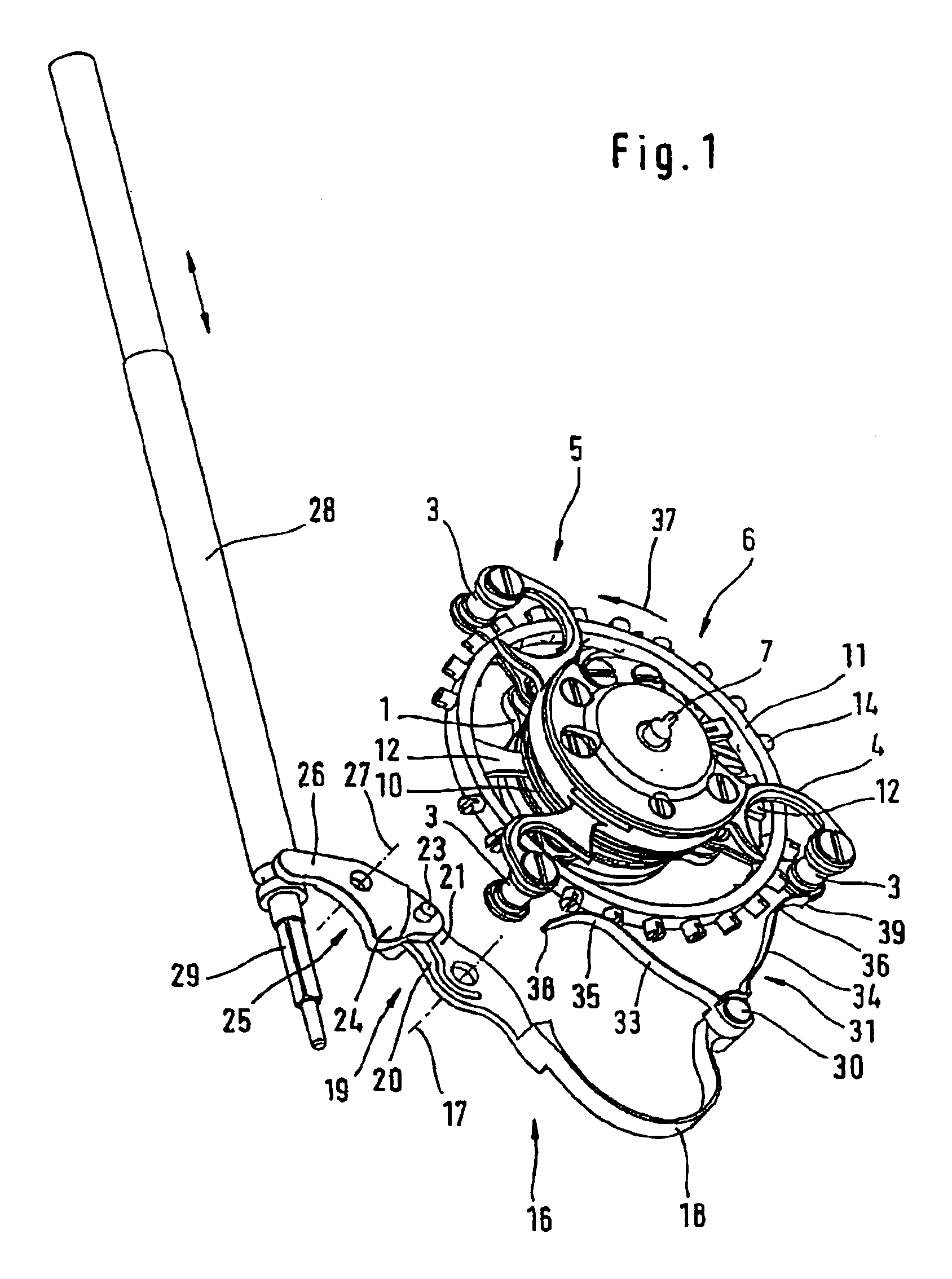
This design, on the one hand, ensures that the stop device is located outside the circulating movement path of the pillars in the normal position and thus does not collide with the circulating cage.
At the same time, the double-arm spring ensures that, when one spring arm bears against a pillar of the cage, the other spring arm can continue to arrest the balance wheel directly.
It is preferable here for the free end of the rear spring arm, as seen in the direction of rotation of the rotary mount, to extend, in the blocking position of the double-arm spring, to a point radially outside the circulating movement path of the pillars, with the result that, even when the free end of this spring arm is located right up against a pillar in the blocking position, this end of the spring arm is prevented from making its way in-between the balance wheel and pillar when the timepiece is restarted. The situation where the free ends of the spring arms catch on the balance wheel, furthermore, is avoided in that the distances between the point of connection and the abutment regions of the two spring arms are different.
If the actuating arm here is of resilient design in the pivoting direction of the pivot lever from the normal position into the blocking position, then this results in a further increase in the possibilities for compensating for the difference spacings of the articulation pin and pivot pin of the balance wheel.

Problems solved by technology

It is not possible to use such an arresting action of the balance wheel in timepieces with a tourbillon, since this results in the stationary spring arm colliding with the circulating cage of the tourbillon.

Method used


Image

  • Tourbillion
  • Tourbillion
  • Tourbillion

Examples


Embodiment Construction

The tourbillon illustrated in the figures has a base plate 1 with three radially outwardly directed arms 2, pillars 3 being arranged vertically at the free ends of said arms 2 and being connected to one another at their top end by a bridge 4, to form a basket-like cage 5. In the center of the cage 5, a circular balance wheel 6 is arranged on a balance staff. One end of the balance staff is mounted on the base plate 1 and the other end is mounted on the bridge 4, with the result that the balance wheel 6 can be pivoted about a pivot pin 7. The balance staff is enclosed by a balance spring 10.

The balance wheel has a balance rim 11 which is connected, via balance legs 12, to the hub 13 of the balance wheel 6 (see FIG. 3), this, in turn, being arranged on the balance staff. The balance rim 11 has balance screws 14, which project radially outwards from the balance rim 11 by way of their screw heads.

Also arranged on the base plate 1 is an escapement comprising a pallet 8 and an escape whee...


PUM


Abstract

A tourbillon for a watch having a setting device for setting the hands of the watch includes a circular balance wheel that can swivel about a swivel axis. In addition, an escapement is provided that consists of a pallet and an escape wheel, the balance wheel and the escapement arranged on a base plate. A balance wheel shaft of the balance is rotationally mounted with its one end on the base plate and with its other end on a cage that surrounds the balance wheel like a basket. The cage comprises, outside of the radially encircling periphery of the balance wheel, a number of interspaced pillars fastened to the base plate and forms, with the base plate, a rotating mount which can be rotationally driven about rotation axis that is coaxial to the swivel axis by a seconds drive of the watch. A stop device can be actuated by the setting device and swiveling movement of the balance wheel can be blocked by the stop device. The stop device has an approximately V-shaped double-arm spring, which can be moved out of a normal position while being radially displaced outside of the encircling movement path of the pillars and into a blocking position in which it can rest in a flexible manner against the radially encircling contour of the balance wheel via contact areas and on both end areas of both of its spring arms that are oriented in and counter to the encircling direction of the contour of the balance wheel.

Description

This is a U.S. national stage of application No. PCT / EP02 / 13107, filed on 22 Nov. 2002. Priority is claimed on that application and on the following application(s): Country: Germany, Application No.: 101 60 287.1, Filed: 07 Dec. 2001.BACKGROUND OF THE INVENTION1. Field of the InventionThe invention relates to a tourbillon for a timepiece, having a setting device for setting the hands of the timepiece, having a circular balance wheel, which can be pivoted about a pivot pin, and with an escapement comprising a pallet and escapement wheel. The balance wheel and the escapement are arranged on a base plate and a balance staff of the balance wheel is mounted in a rotatable manner, by way of one end, on the base plate and, by way of its other end, on a cage which encloses the balance wheel in a basket-like manner and which has, outside the radially circulating periphery of the balance wheel, a plurality of pillars spaced apart from one another on the base plate and forms, together with the...

Claims


Application Information

Patent Timeline
IPC IPC(8): G04B27/00G04B17/00G04B17/28
CPCG04B27/004G04B17/285
Inventor GEYER, HELMUT
Owner LANGE UHREN
Learn More