
Mobile bulletproof personnel shield

a technology of bulletproof personnel shield and mobile body, which is applied in the direction of shields, protective equipment, weapons, etc., can solve the problems of not always being satisfied, blunt trauma injuries, and blunt trauma injuries in areas near vital organs can be serious or even life-threatening problems

Inactive Publication Date: 2005-01-25
DRACKETT JOHN W
View PDF20 Cites 44 Cited by
  • Summary
  • Abstract
  • Description
  • Claims
  • Application Information

AI Technical Summary

Problems solved by technology

Police and security forces all over the world are confronted with the problem of controlling crowds and demonstrations which at times become violent.
Wars, insurrections, riots, and police actions of various kinds often involve small arms fire and projectiles in which people are often injured or wounded while in an exposed position.
These have not always been found satisfactory when crowds become very large or exceedingly aggressive and throw objects, such as bottles and stones, and in the face of shots from small arms.
Although the layers of fiber are able to prevent most bullets fired from pistols from penetrating, the impact of the projectile causes the fabric to bend inward against the body, creating blunt trauma injuries.
Blunt trauma injuries in areas near vital organs can be a serious or even life threatening problem.
Body armor designed to protect against higher threat levels, such as 12 gauge rifled slugs and high powered rifles, is very cumbersome and is not worn on a day to day basis by police officers.
In addition to this limitation, the body armor usually worn by police officers offers no protection at all for the head, neck, arms and legs.
We are not aware of any other design that offers such a high degree of protection and mobility.
The handheld shields used by SWAT teams are mobile, but offer no protection from attacks on either side, overhead or from frontal attacks to the legs.
Currently, there is a huge gap between these handheld shields, and heavy, massive armored vehicles that can not move through a small alley, a wooded area, between parked cars or enter a building.
Unlike other designs that employ curved metal, the ballistic fabric covering will not cause bullets to ricochet off the surface, an extremely dangerous situation.

Method used


Image

  • Mobile bulletproof personnel shield
  • Mobile bulletproof personnel shield
  • Mobile bulletproof personnel shield

Examples


Embodiment Construction

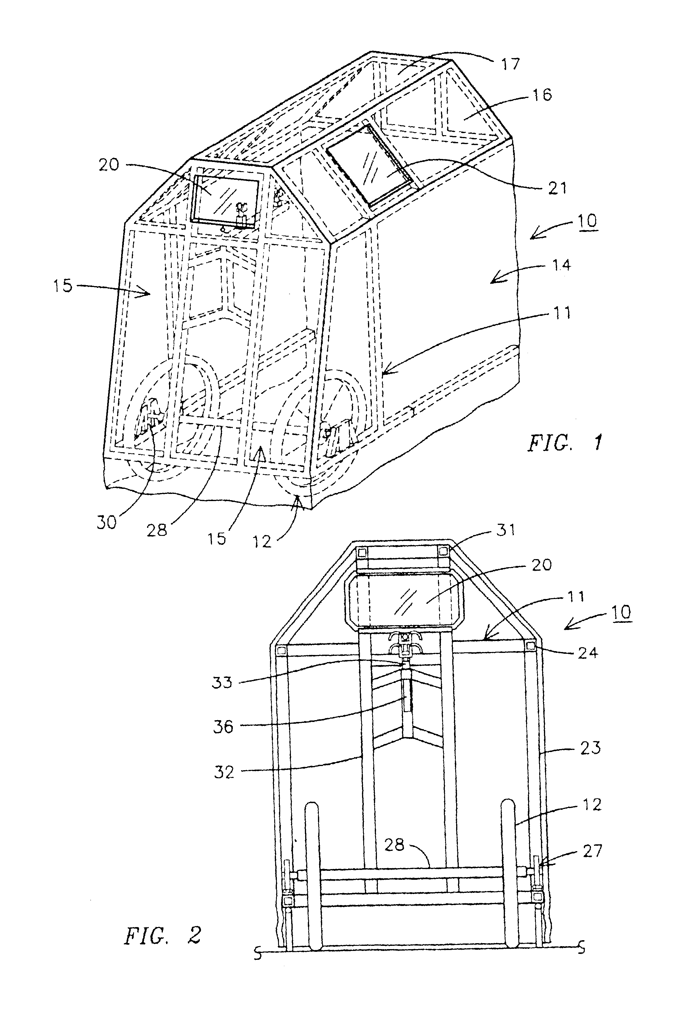
Referring to the drawings FIGS. 1-5, a mobile personnel gunfire shield 10 is illustrated having a framework 11 which may be formed of any satisfactory material desired, such as steel or aluminum. The frame is supported on large front wheels 12 to allow the frame to be rolled by an individual 13. The frame supports a flexible ballistic shielding material 14 on the sides thereof and shielding material 15 on the front. The shielding material also covers top areas 16 and 17. The flexible shielding material can be a woven Kevlar or similar polymer shield material commonly used in bulletproof vests and is loosely attached to the metal frame 11 so that when a projectile, such as a bullet, hits the material 14 and 15, the material stops the projectile. The material is spaced from the individual which allows the fabric to move or give during the dissipation of the energy from a projectile. A bulletproof glass or polymer window 20 is also mounted in the shield 10. There is also an angled bull...


PUM


Abstract

A mobile personnel gunfire shield apparatus has a frame supported on a pair of large wheels. The frame has a bullet resistant window mounted therein and is covered with flexible ballistic shield material, such as woven Kevlar, removably attached to the frame. A movable gun mount is mounted to the frame front adjacent the window mounted therein and has a gun having a barrel removably mounted thereto with the barrel extending through an opening in the front of the flexible ballistic shield material which allows a person to move the gunfire shield while protecting the occupant from gunfire and simultaneously operate the gun from thereinside.

Description

BACKGROUND OF THE INVENTIONThe present invention generally relates to a mobile bullet resistant personnel shield and especially to a hand maneuverable wheeled bullet resistant shield for use by security forces, police, militia and by the military to protect individuals from gunfire.Police and security forces all over the world are confronted with the problem of controlling crowds and demonstrations which at times become violent. The military is faced with protecting military personnel from bullets and shrapnel while in exposed positions. Wars, insurrections, riots, and police actions of various kinds often involve small arms fire and projectiles in which people are often injured or wounded while in an exposed position. Security forces typically have at their disposal helmets, billy sticks, and hand-held protective shields. These have not always been found satisfactory when crowds become very large or exceedingly aggressive and throw objects, such as bottles and stones, and in the fa...

Claims


Application Information

Patent Timeline
Patent Type & Authority Patents(United States)
IPC IPC(8): F41H5/14F41H5/00
CPCF41H5/14
Inventor DRACKETT, JOHN W.
Owner DRACKETT JOHN W
Learn More