
Drive apparatus

a drive apparatus and drive shaft technology, applied in piezoelectric/electrostrictive/magnetostrictive devices, piezoelectric/electrostrictive/magnetostriction machines, piezoelectric/electrostrictive/magnetostrictive devices, etc., can solve the problem of large rush-current flows, power consumption becomes high, and the suppressing effect of rush-current is not sufficient, so as to achieve accurate driving. the effect of easy and efficient execution

Inactive Publication Date: 2005-01-18
MINOLTA CO LTD
View PDF10 Cites 14 Cited by
  • Summary
  • Abstract
  • Description
  • Claims
  • Application Information

AI Technical Summary

Benefits of technology

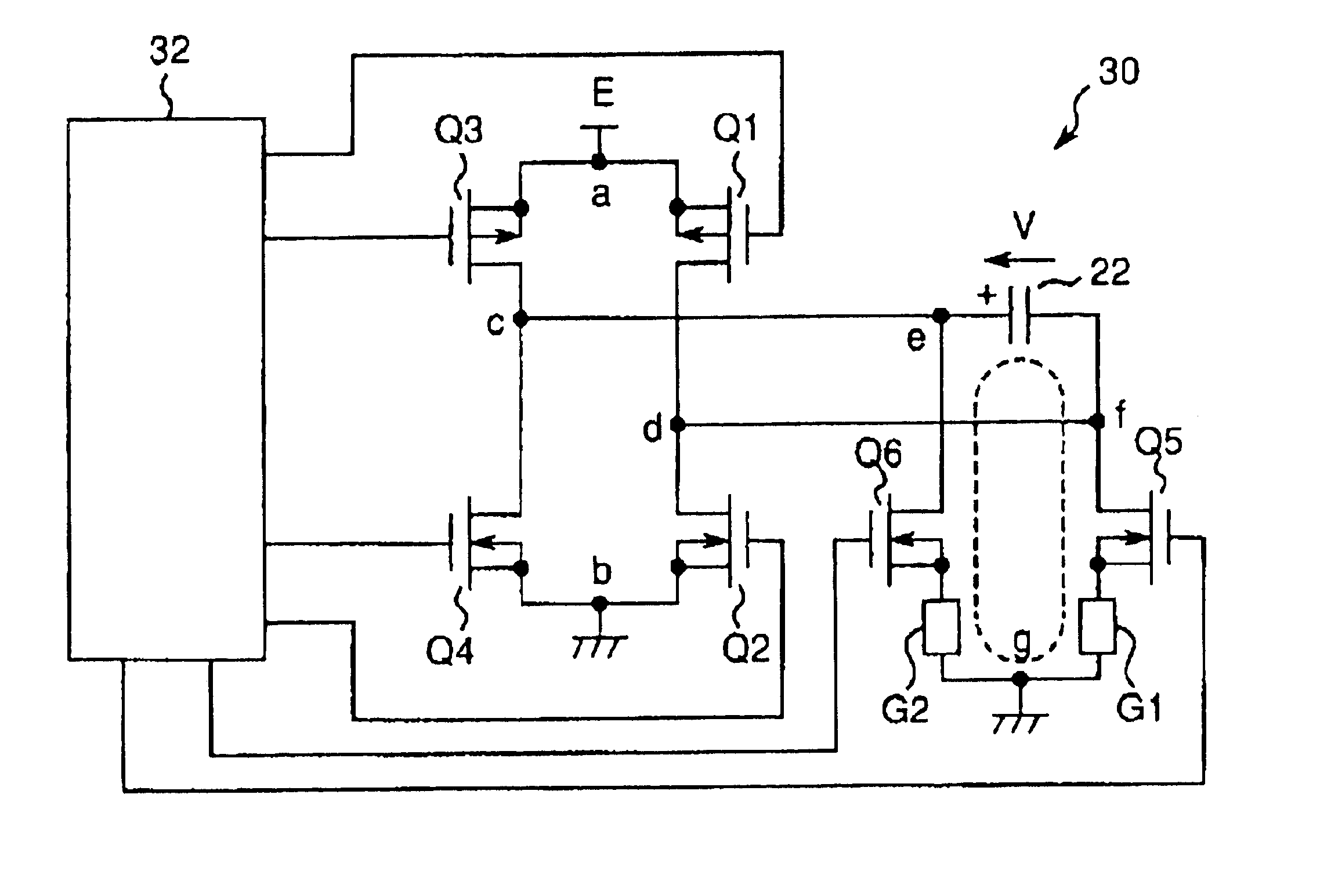
According to the above structure, since it is not necessary to provide the switching means for operating the discharging circuit separately from the drive circuit, the structure of the drive apparatus can be simplified.
With the above structure, a voltage can be applied to the capacitive load at the first peak or its vicinity after the discharging circuit is operated and a voltage of the capacitive load is inverted. As a result, an insufficient voltage can be small as much as possible when a voltage is applied to the capacitive load, thereby driving the drive apparatus efficiently.
With the above structure, accurate driving can be executed easily and efficiently.

Problems solved by technology

For this reason, in a drive apparatus having the conventional structure, when an applying voltage of the piezoelectric element 122 is switched for driving, there arises a problem that a large rush-current flows and power consumption becomes high.
(r is a general resistance value of an ON resistance of FET, an output resistance of a power source, a line resistance or the like), namely, the rush-current I is reduced to half, but a suppressing effect of a rush-current is not sufficient.

Method used


Image

  • Drive apparatus
  • Drive apparatus
  • Drive apparatus

Examples


second embodiment

Next, there will be explained below the drive apparatus according to the present invention with reference to FIGS. 5 and 6.

The drive apparatus according to the second embodiment is constituted approximately similarly to the drive apparatus of the first embodiment, but there is a difference such that the switching elements Q5 and Q6 in FIG. 3 are omitted and the switching elements Q2 and Q4 serve also as them. The following will mainly explain the different point using the like reference numerals for the like components.

FIG. 5 shows a drive circuit 30a of the drive apparatus according to the second embodiment. The drive circuit 30a omits a switching element for a discharging circuit and includes four switching elements Q1, Q2, Q3 and Q4, inductive elements G1 and G2 and a control circuit 32a. The switching elements Q1 through Q4 compose the first and second drive circuits approximately similarly to the first embodiment. Differently from the first embodiment, the inductive element G1 ...


PUM


Abstract

In order to provide a drive apparatus where a rush-current is small when a voltage is applied to a capacitive load so that the drive apparatus is driven, the drive apparatus has a capacitive load 22, first drive circuits Q1, Q4 for applying a power source voltage E to the capacitive load 22, second drive circuits Q2, Q3 for applying the power source voltage E to the capacitive load 22 to an opposite direction to the first drive circuits Q1 and Q4, and a control circuit 32 for operating the first and second drive circuits Q1, Q4; Q2, Q3 alternately. Discharging circuits Q5, G1, G2, Q6 which are connected with inductive element G1 and G2 are provided to both ends of the capacitive load 22. The control circuit 32 operates the first and second drive circuits Q1, Q4; Q2, Q3 with an interval, and operates the discharging circuits Q5, G1, G2, Q6 during the interval.

Description

This application is based on application No. JP 2001-341812 filed in Japan, the contents of which is hereby incorporated by reference.BACKGROUND OF THE INVENTION1. Field of the InventionThe present invention relates to an improved drive apparatus. More specifically, the invention relates to the improved drive apparatus which is driven by applying an alternating voltage to a capacitive load. As one concrete application example, the capacitive load is an electromechanical transducing element.2. Description of the Related ArtConventionally, a drive apparatus using a piezoelectric element is provided. Such a drive apparatus is driven by a drive circuit 70 as shown in FIG. 8, for example. In the drawing, 72 is a control circuit, 122 is a piezoelectric element as a capacitive load, F1 and F3 are P-channel FETs (field-effect transistors) for driving, and F2 and F4 are N-channel FETs for driving.FIG. 9 is a timing chart showing an operating sequence. FIGS. 9(a) through 9(d) show gate voltag...

Claims


Application Information

Patent Timeline
Patent Type & Authority Patents(United States)
IPC IPC(8): H01L41/00H01L41/04H01L41/09H02N2/00
CPCH02N2/067H02N2/025
Inventor HOSHINO, TAKAYUKI
Owner MINOLTA CO LTD
Learn More