
Dual level inverted portal axle lubrication configuration

Active Publication Date: 2005-01-18
ARVINMERITOR TECH
View PDF9 Cites 25 Cited by
  • Summary
  • Abstract
  • Description
  • Claims
  • Application Information

AI Technical Summary

Benefits of technology

The present invention therefore provides an inverted portal axle configuration which assures a proper quantity of oil in both the wheel ends and the axle, while reducing the total quantity of oil and maintain a low floor profile to improve vehicle access.

Problems solved by technology

Disadvantageously, the inverted portal axle configuration requires a relatively large volume of lubricant within the axle.
Such a relatively large volume of lubricant adds significantly to the axle weight.
In some instances, vehicle operation may force lubricant out of the wheel ends and into the axle which may result in spinout damage to the wheel end gear train.

Method used


Image

  • Dual level inverted portal axle lubrication configuration
  • Dual level inverted portal axle lubrication configuration
  • Dual level inverted portal axle lubrication configuration

Examples


Embodiment Construction

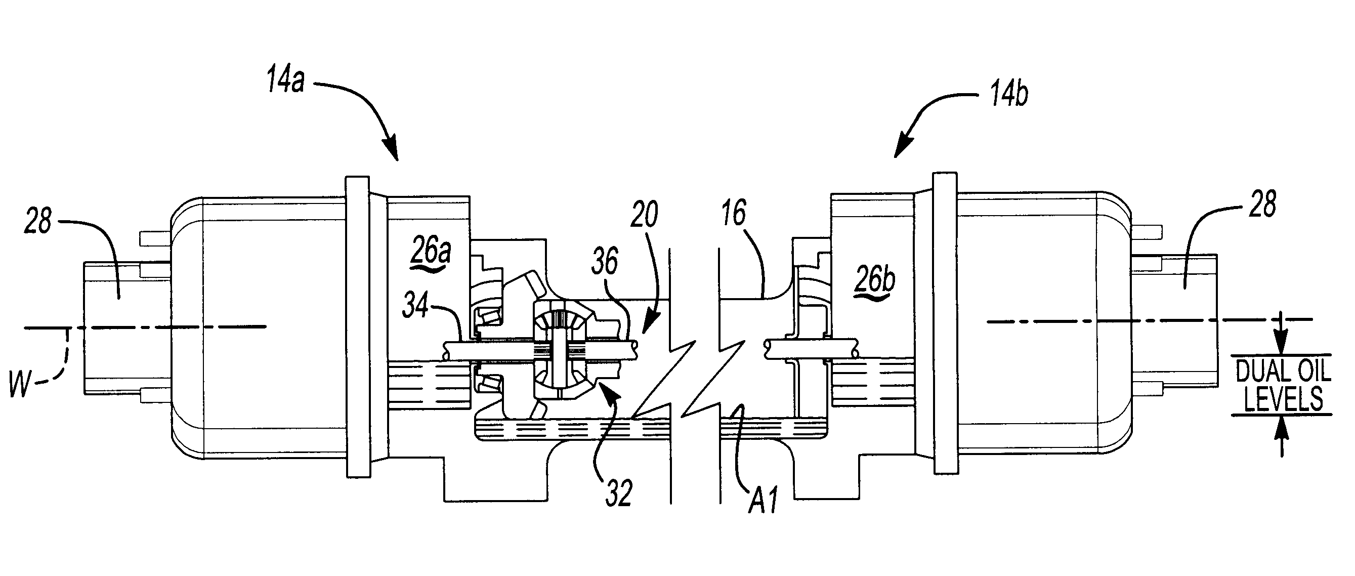
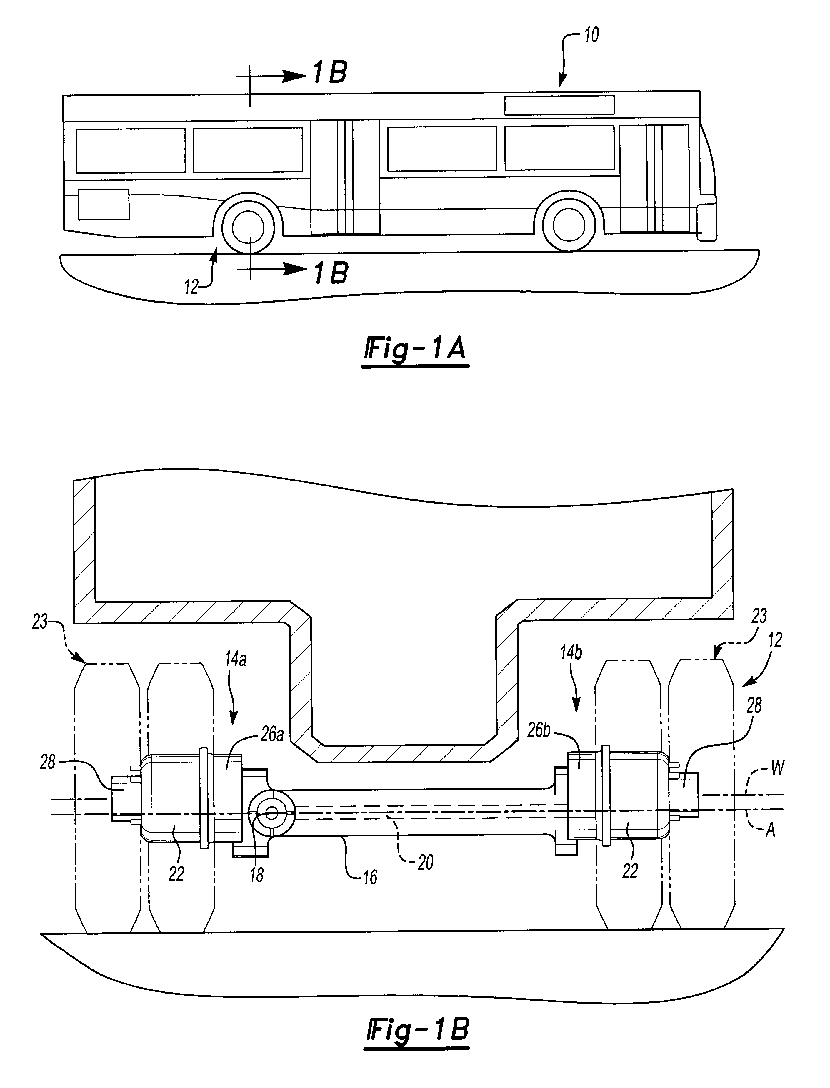
FIGS. 1A and 1B schematically illustrate a vehicle 10 incorporating an inverted portal axle system 12. The inverted portal axle 12 includes a pair of wheel end assemblies 14A, 14B interconnected by an axle housing 16. An input 18 is positioned near one of the wheel end assemblies 14A, 14B and a shaft assembly 20 connects the input 18 to the other wheel end assembly 14A, 14B. The shaft 20 defines an axle axis of rotation A.

Each wheel end assembly 14A, 14B includes a wheel hub assembly 22 driven by a gear reduction (illustrated schematically at 26A,26B). The gear reduction 26A,26B drives a spindle 28 (also illustrated in FIG. 2) which drives the wheel hub assembly 22 and tires 23. The gear reduction 26A, 26B includes gearing to transfer the torque from the axle assembly 20 to the spindle 28 through the gear reduction 26A, 26B. The spindles 28 defines a wheel axis of rotation W. The wheel axis of rotation W is higher relative to the ground than the axle axis of rotation A. Tires 23 are...


PUM


Abstract

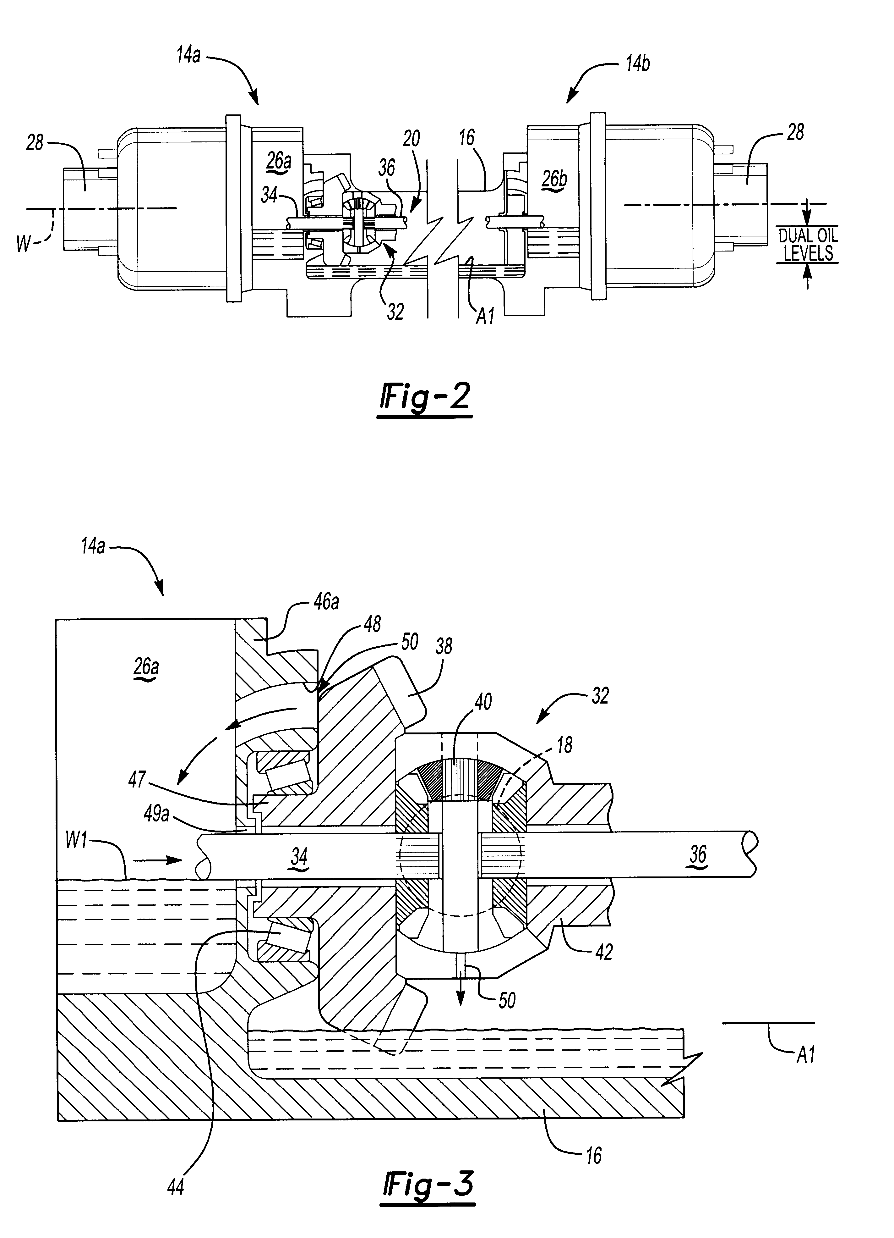
An axle system includes an axle lubrication level within an axle housing which is lower than a wheel end lubrication level within the wheel end assemblies. An opening through the wheel end assembly housing provides a fluid communication path between the wheel end assembly and the axle housing. A differential assembly rotates adjacent an opening such that lubrication at the wheel end lubrication level is rotated into the opening. The lubricant within the wheel end assemblies is maintained at the wheel end lubrication level. The shaft enters the wheel end assembly housing through a shaft opening which provides a communication path for the lubricant from the wheel end assembly back into the axle housing.

Description

BACKGROUND OF THE INVENTIONThe present invention relates to an inverted portal axle configuration, and more particularly to a lubrication system therefore.Mass transit vehicles, such as trolley cars, buses, and the like typically have seats aligned at the lateral sides of the vehicle, with a central aisle and floor extending along the vehicle. In order to facilitate entering and exiting from the vehicle, it is desirable to have the vehicle floor and aisle positioned relatively low to the ground. This provides faster cycle time at bus stops.Many such vehicles provide a rigid axle having a gear box at each longitudinal end to form an inverted portal axle configuration. The inverted portal axle configuration is particularly effective in providing a low floor vehicle.Disadvantageously, the inverted portal axle configuration requires a relatively large volume of lubricant within the axle. The large volume of lubricant requires the rotating shaft within the rigid axle to be almost complet...

Claims


Application Information

Patent Timeline
IPC IPC(8): B60B35/00B60K17/16F16H57/04
CPCB60B35/002B60B35/163B60K17/16F16H57/0447F16H57/0483B60B2900/111B60B2900/212B60Y2200/1432Y10T74/2188F16H57/0445F16H57/0457F16H2057/02052F16H57/0427Y02T10/86
Inventor HAYES, BRIAN DAVIDVARELA, TOMAZ DOPICOSULLIVAN, WILLIAM C.
Owner ARVINMERITOR TECH
Learn More