
Method and apparatus for interconnecting wired-AND buses

a technology of interconnection and wired and bus, applied in the field of buses, can solve the problems of not being tested and verified, complicated situation, and difficulty in ensuring reliable operation in the presence of multiple master implementations designed by different vendors, so as to improve the ability of technicians to diagnose problems and maximize the ability to isolate faults.

Inactive Publication Date: 2005-01-11
ORACLE INT CORP
View PDF27 Cites 38 Cited by
  • Summary
  • Abstract
  • Description
  • Claims
  • Application Information

AI Technical Summary

Benefits of technology

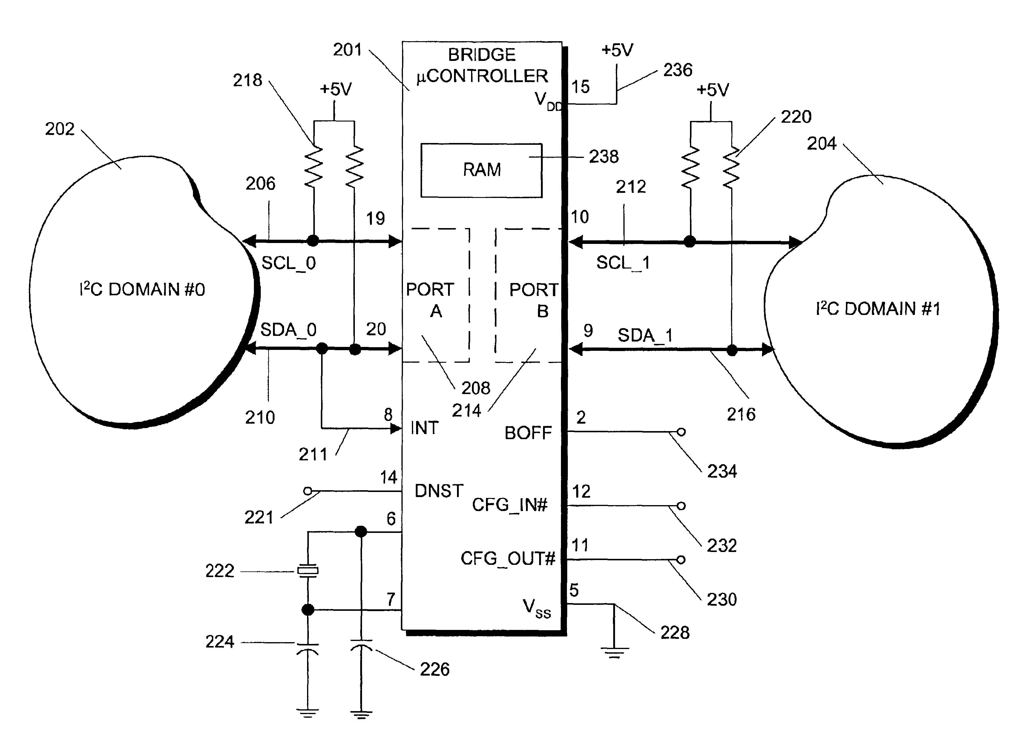
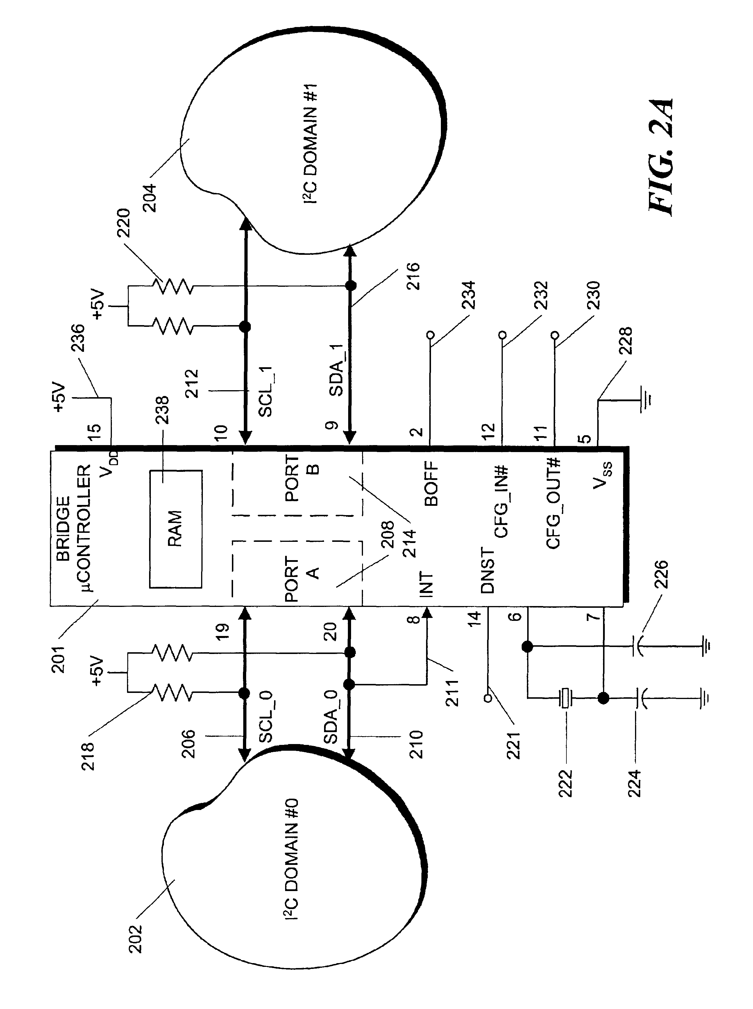
[0013]In accordance with the principles of the invention, one or more bus bridges are used to partition a large I2C bus into smaller bus segments. By programming address bitmaps that are internal to each bridge, the various bus segments can be made to appear as one logical bus. In addition, the bus topology can be designed to maximize the ability to isolate faults within a given segment, thereby improving the ability of technicians to diagnose problems in very large I2C implementations.

Problems solved by technology

While a simple single-master system using the I2C technology works well, the situation becomes much more complicated when much larger and more complex I2C subsystems involving multiple unique master devices and dozens of slave devices on a single bus are constructed.
Perhaps the biggest challenge in the design of any large multi-master I2C subsystem is the difficulty of ensuring reliable operation in the presence of multiple master implementations designed by different vendors.
Since most I2C devices are used in simple single-master bus implementations, many available I2C master devices which claim to support multi-master operation have not been tested and verified sufficiently to be used together reliably on a single I2C bus.
Furthermore, the wire-AND nature of the I2C bus means that a failure of any one device can cause the entire bus to fail, leading to difficulties in isolating the cause and nature of the fault that caused the bus failure.
In addition, one of the fundamental signal integrity challenges in any large I2C system design is meeting the rise-time specification of one microsecond on the SDA and SCL signals.
Further, the strength of the pull-up resistor is limited by the maximum current that the output cells on I2C components can sink, which is stated in the aforementioned I2C specification as 3 ma.
These design constraints limit both the number of master and slave devices on the bus as well as the physical length of the bus, making large I2C system designs very challenging.

Method used


Image

  • Method and apparatus for interconnecting wired-AND buses
  • Method and apparatus for interconnecting wired-AND buses
  • Method and apparatus for interconnecting wired-AND buses

Examples


Embodiment Construction

[0028]The invention concerns a bus bridge apparatus and method that buffers I2C transactions generated on one I2C bus by a bus master and retransmits the transactions on another bus segment. During this retransmission, the I2C address may also be filtered and translated. In one embodiment, the bridge is implemented by one or more unidirectional devices; there are several different configurations in which the bridge devices can be used. For example, a single bridge device could be used to provide electrical isolation and loading isolation between two I2C domains where the transaction flow from one domain to the other is always unidirectional. Alternatively, multiple bridge devices could be placed as “peers” on a top-level bus with the system's main I2C controller, connecting to a set of downstream I2C buses, thus implementing a tree topology.

[0029]In a single unidirectional bridge application, two I2C domains are separated by a bridge constructed, as described below, with a single mi...


PUM


Abstract

One or more bus bridges are used to partition a large I2C bus into smaller bus segments. By programming address bitmaps that are internal to each bridge, the various bus segments can be made to appear as one logical bus. In addition, the bus topology can be designed to maximize the ability to isolate faults within a given segment, thereby improving the ability of technicians to diagnose problems in very large I2C implementations. In one embodiment, the invention is a unidirectional bus bridge which is designed so that two such bridges can be used in parallel (facing in opposite directions) to implement a fully bi-directional bus bridge. In another embodiment, I2C slave addresses are replicated in a single logical I2C bus by addressing a tunnel command to a bridge, which command contains an address and causes the bridge to which it is addressed to forward the contained address.

Description

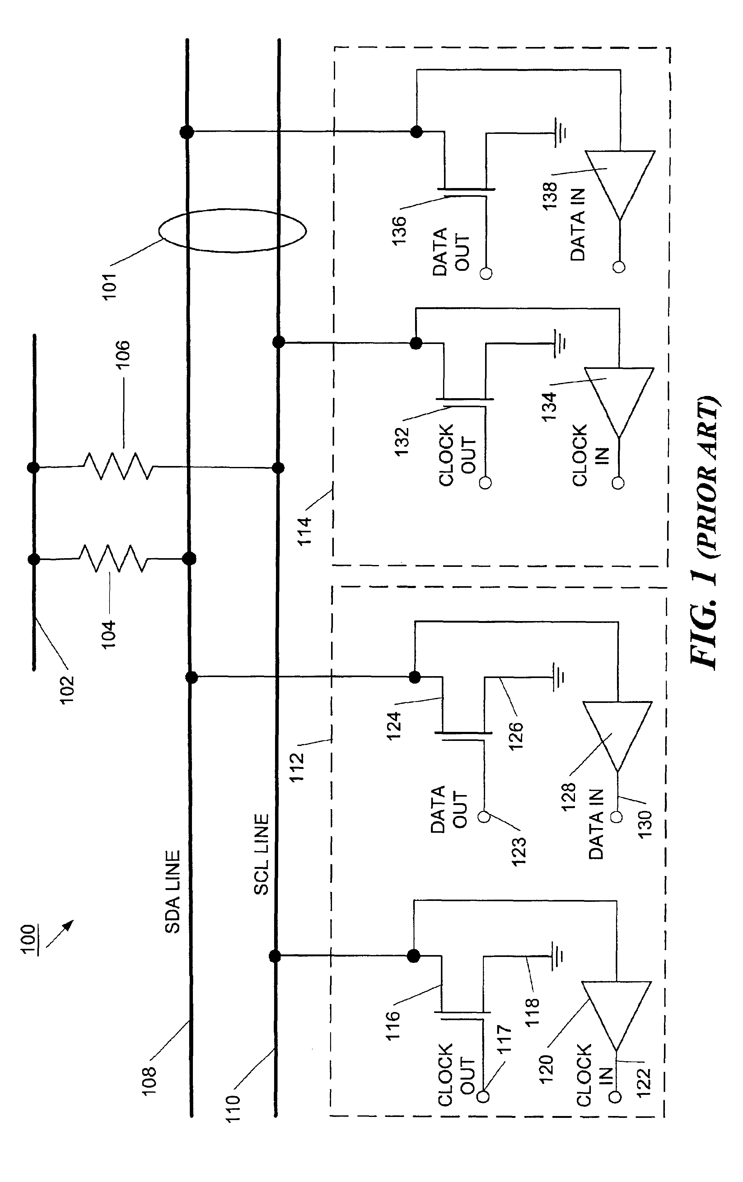
FIELD OF THE INVENTION[0002]This invention relates to buses using a wired-AND protocol and, more particularly, to methods and apparatus for interconnecting having two or more such buses.BACKGROUND OF THE INVENTION[0003]The I2C bus system is an electronic bus for carrying commands and data between compatible devices connected to the bus. The system was developed and marketed by Philips Semiconductor Corporation and is described in detail in the I2C Specification, revision 2.0, Philips Semiconductor Corporation 1998, which specification is hereby incorporated by reference in its entirety. In the I2C bus system, two wires, called a serial data (SDA) line and serial clock (SCL) line, carry information between the devices connected to the bus. Both the SDA and SCL lines are bi-directional lines, connected to a positive supply voltage via pull-up resistors as shown in FIG. 1 to form a “wired-AND” configuration. For example, in the bus configuration 100 illustrated in FIG. 1, the SDA line ...

Claims


Application Information

Patent Timeline
IPC IPC(8): G06F13/40
CPCG06F13/404G06F13/4022
Inventor ERVIN, JOSEPH J.
Owner ORACLE INT CORP
Learn More