
Cutting tool and cutting insert therefor

a cutting tool and insert technology, applied in metal-working equipment, metal-working equipment, milling equipment, etc., can solve the problems of high cost and time-consuming of insert seat production and tight tolerances of insert sea

Inactive Publication Date: 2005-01-11
ISCAR LTD
View PDF14 Cites 51 Cited by
  • Summary
  • Abstract
  • Description
  • Claims
  • Application Information

AI Technical Summary

Benefits of technology

Typically, in a top view the cutting insert has a generally parallelogrammatical shape defining a pair of long cutting edges, a pair of short cutting edges, transversely directed to and extending from the long cutting edges, and a pair of rounded cutting edges, each of the rounded cutting edges extends between a long cutting edge and a short cutting edge.
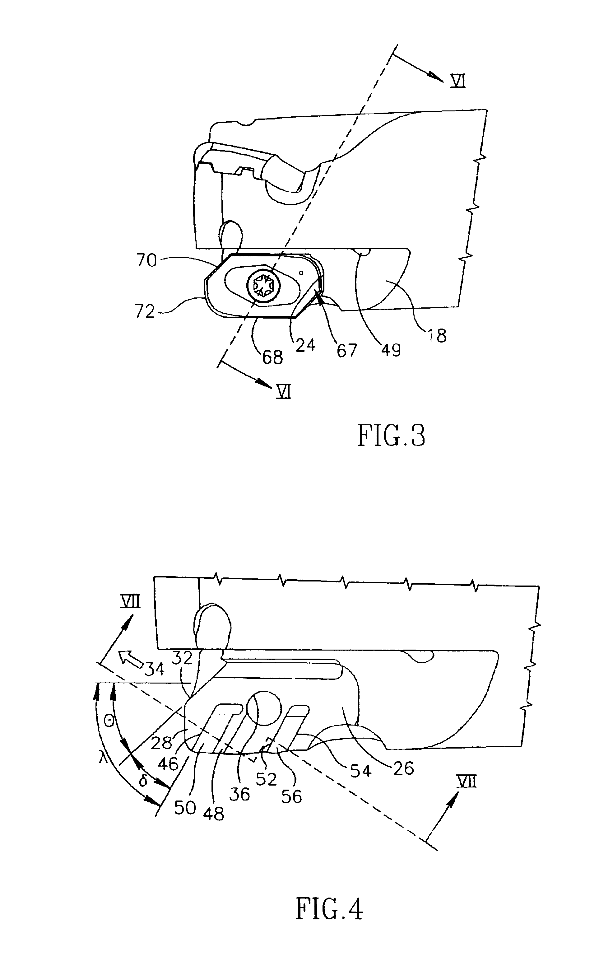
Further typically, the short cutting edges are slanted at an acute sixth angle (θ1) with respect to the longitudinal axis (B) of the cutting insert, the sixth angle (θ1) being in the range of 20° to 60°.

Problems solved by technology

Any production of the insert and the insert seat in tight tolerances is expensive and time consuming.

Method used


Image

  • Cutting tool and cutting insert therefor
  • Cutting tool and cutting insert therefor
  • Cutting tool and cutting insert therefor

Examples


Embodiment Construction

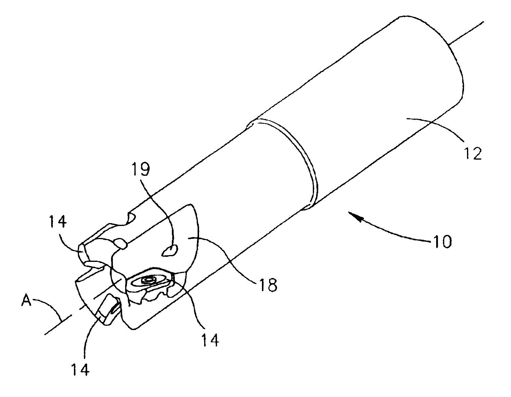
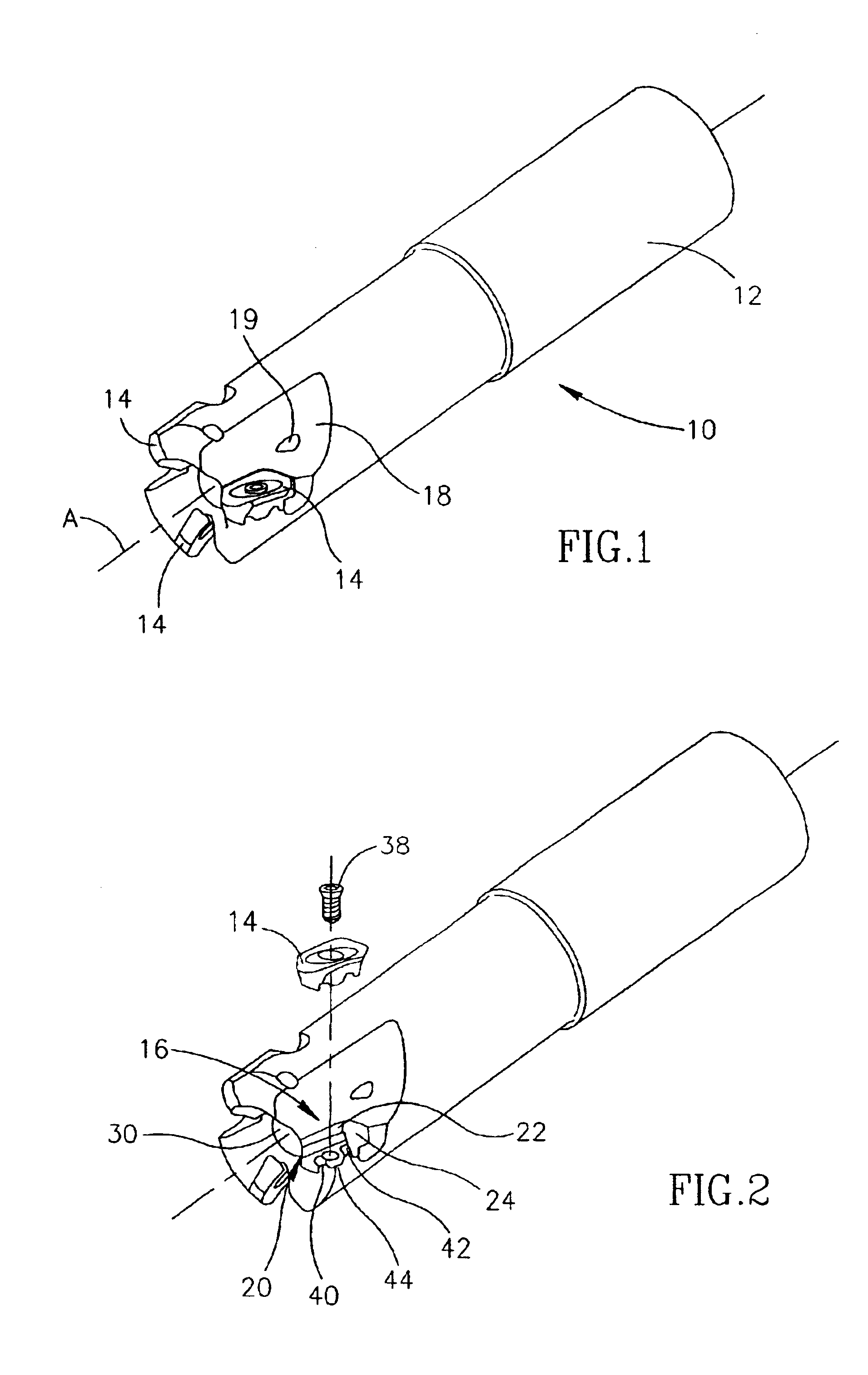
Attention is drawn to FIGS. 1 to 12. As shown, a cutting tool 10, having an axis of rotation A, comprises an insert holder 12 and three cutting inserts 14 mounted within equally peripherally distributed insert receiving pockets 16 formed in a front portion of the insert holder 12. Each of the insert receiving pockets is associated with a chip gullet 18 and with a coolant through bore 19. In the described embodiment of the cutting tool 10 three cutting inserts are used. However, it is understood that the invention is equally applicable to any cutting tool using at least one cutting insert. All the cutting inserts 14 and the insert receiving pockets 16 are equal therefore only one of them will be described.

Each of the insert receiving pockets 16 comprises a longitudinally extending inner wall 20 substantially co-directional with the axis of rotation A. An upper portion of the inner wall 20 is flat and constitutes a radial abutment surface 22. The radial abutment surface 22 does not ha...


PUM

PropertyMeasurementUnit
angleaaaaaaaaaa
second angleaaaaaaaaaa
angleaaaaaaaaaa

Abstract

A cutting tool has an insert holder provided with an insert receiving pocket and at least one cutting insert mounted therein. The insert receiving pocket has a longitudinally extending inner wall, a rear wall adjacent the inner wall and a lower wall adjacent the inner wall and the rear wall. A front end of the lower wall protrudes forwardly with respect to a central portion of the insert holder. A front protrusion rises upwardly from the lower wall and extends inwardly and rearwardly from a periphery of the insert holder. The front protrusion has a front surface perpendicular to the lower wall. A groove formed in the bottom surface of the cutting insert has a distal side wall perpendicular to the bottom surface. When assembled, a radial abutment surface of the cutting insert abuts a radial abutment surface of the insert receiving pocket, the front surface of the front protrusion abuts the front distal side wall of the groove and a rear portion of the one cutting insert is spaced from the rear wall of the insert receiving pocket.

Description

FIELD OF THE INVENTIONThe present invention relates to a cutting tool and a cutting insert therefor for use particularly in ramp-down operations.BACKGROUND OF THE INVENTIONCutting tools for performing ramp-down operations are known. Such cutting tools are, usually, end mills and face mills. In these cutting tools, at least one cutting insert is mounted and retained within an insert receiving pocket located in a front portion of an insert holder. During a cutting operation, when a side cutting edge is operative, the radial cutting forces acting on the cutting insert are directed generally radially inwardly thereby urging the cutting insert against a radial abutment surface. Thus, the cutting forces contribute to securing the cutting insert within the insert receiving pocket. Similarly, when a front cutting edge is operative, the axial cutting forces acting on the cutting insert are directed generally axially rearwardly thereby urging the cutting insert against an axial abutment surfa...

Claims


Application Information

Patent Timeline
Patent Type & Authority Patents(United States)
IPC IPC(8): B23C5/20B23C5/10B23C5/16B23C5/00B23C5/22
CPCB23C5/109B23C5/2221B23C2200/165Y10T407/1908Y10T407/23Y10T407/2274B23C2210/168B23C5/2213B23C2200/284B23C5/20
Inventor MORGULIS, RAFAELBABUSHKIN, ANTON
Owner ISCAR LTD
Learn More