Power hammer puller

a technology of hammer and shaft, which is applied in the direction of metal-working equipment, metal-working equipment, manufacturing tools, etc., can solve the problems of personal injury, scoring of the shaft on which the bearing is mounted, etc., and achieve the effect of quick, easy and efficient removal of the bearing from the shaft and little, if any, of injury to the individual

Inactive Publication Date: 2005-01-11
DUDECK MARTIN J
View PDF6 Cites 6 Cited by
  • Summary
  • Abstract
  • Description
  • Claims
  • Application Information

AI Technical Summary

Benefits of technology

The power hammer puller utilizes an air hammer to quickly, easily and efficiently remove a bearing from a shaft. With the use of this device there is very little, if any, risk of injury to the individual as well as very little, if any, risk of injury to the piece of mechanical equipment.

Problems solved by technology

However, an air hammer is necessary to operate this device.
This of course can lead to personal injury as well as scoring of the shaft upon which the bearing sits.

Method used


Image

  • Power hammer puller
  • Power hammer puller
  • Power hammer puller

Examples


Embodiment Construction

The device is a cylindrical tube with a bit on the end plate and a mechanism to allow a claw to be inserted on the opposite end. A pneumatic hammer is inserted in the hollowed part of the tube and over the bit, which is at the opposite end of the claw. As the pneumatic hammer is operated the claw pulls a bearing, for instance, off a shaft.

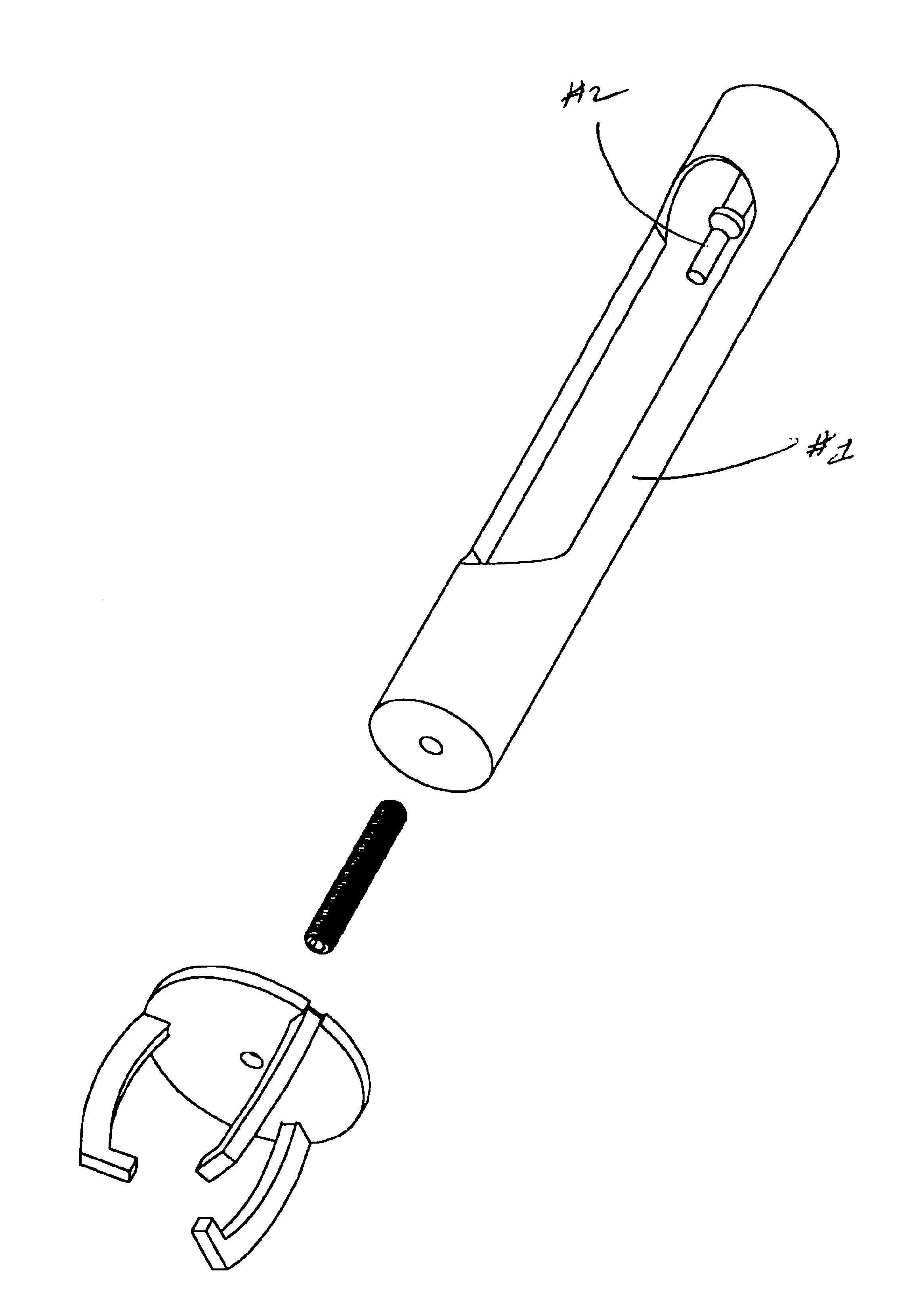
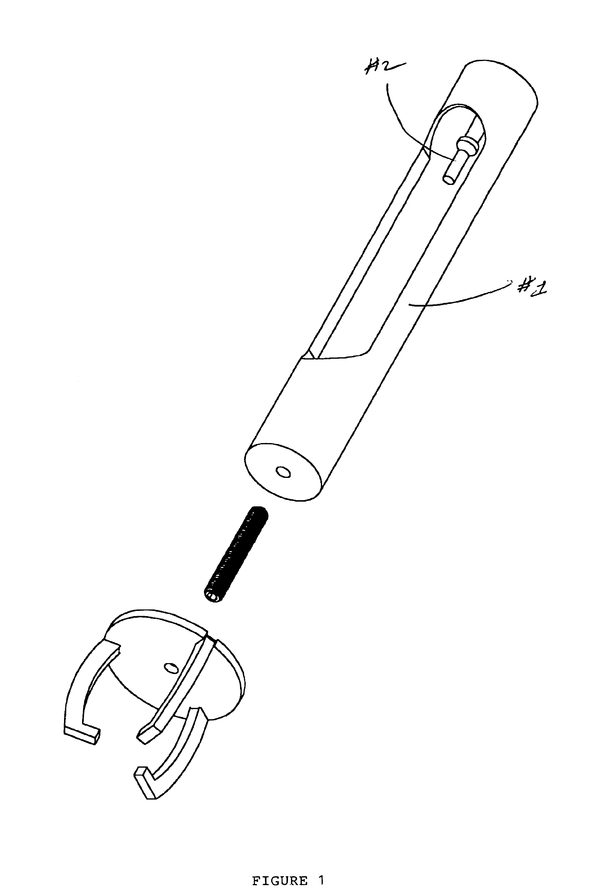
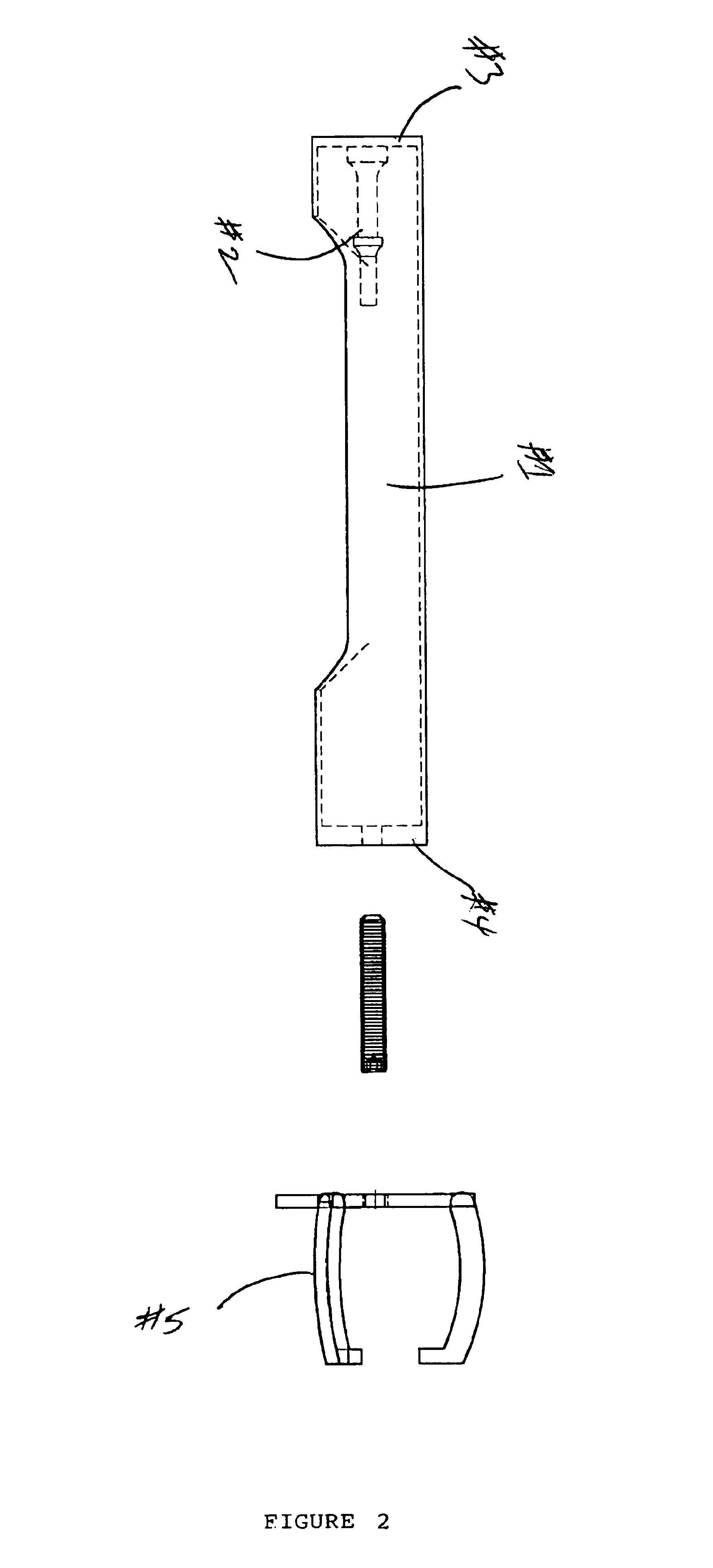
According to FIG. 1, the device itself is the tube (#1). Integral to the device is the end plate which contains the bit (#2) FIG. 1. There are tow end plates (#3 and #4) (FIGS. 2, 3, and 4). One of the end plates (#3) houses the bit (#2), which is used in this device. A standard air hammer is placed over the bit. The bit (#2) which is part of the device is flanged or welded to the end plate. (#3).

Another end plate (#4) is used in this device. The purpose of this end plate, which is tapped and threaded, is to pull the bearing off the shaft, FIG. 2 depicts a representation of a typical “claw” (#5), which pulls bearings from shafts. The claw itself is...


PUM

PropertyMeasurementUnit
forceaaaaaaaaaa
sizeaaaaaaaaaa
forcesaaaaaaaaaa

Abstract

The embodiment of this invention is disclosed which describes a power hammer puller to remove items from a shaft. The device consists of a cylindrical tube into which an air hammer fits. A bit is installed on one end of the tube and the other end is threaded to allow items to be removed from shafts. While the embodiments of the invention have been disclosed, certain modifications may be made by those skilled in the art to modify the various size of the tube as well as the size of the bit or the size of the standard threaded hole to accommodate particular applications.

Description

CROSS REFERENCES TO RELATED APPLICATIONSNoneReference to AppendixNo appendix accompanies this applicationBACKGROUND OF THE INVENTIONThis invention relates to a device, which would help individuals, such as mechanics, to remove items such as bearings from shafts. Any individual could use the device and the user need not be a mechanic to use this device. The device is also not limited to the removal of bearings but this is a potential use. This device utilizes an air hammer, and for an example a claw mechanism to remove the bearing from the shaft.The claw mechanism and the air hammer are not necessary parts of the invention but illustrate how the device is to be used. However, an air hammer is necessary to operate this device.The specific item that is being claimed is a tube, which contains a bit on one end and a flat surface, which is threaded, on the opposite end. The tube is cylindrical but is hollowed along one side of the tube. It is hollowed to accommodate an air hammer. The air...

Claims


Application Information

Patent Timeline
Patent Type & Authority Patents(United States)
IPC IPC(8): B25B27/02
CPCB25B27/02Y10T29/53952Y10T29/53843Y10T29/53896
Inventor DUDECK, MARTIN J.
Owner DUDECK MARTIN J
Why Eureka
Try Eureka