Debug interface for an event timer apparatus
- Summary
- Abstract
- Description
- Claims
- Application Information
AI Technical Summary
Benefits of technology
Problems solved by technology
Method used
Image
Examples
Embodiment Construction
The illustrative embodiments of the present invention will be described with reference to the Figure drawings.
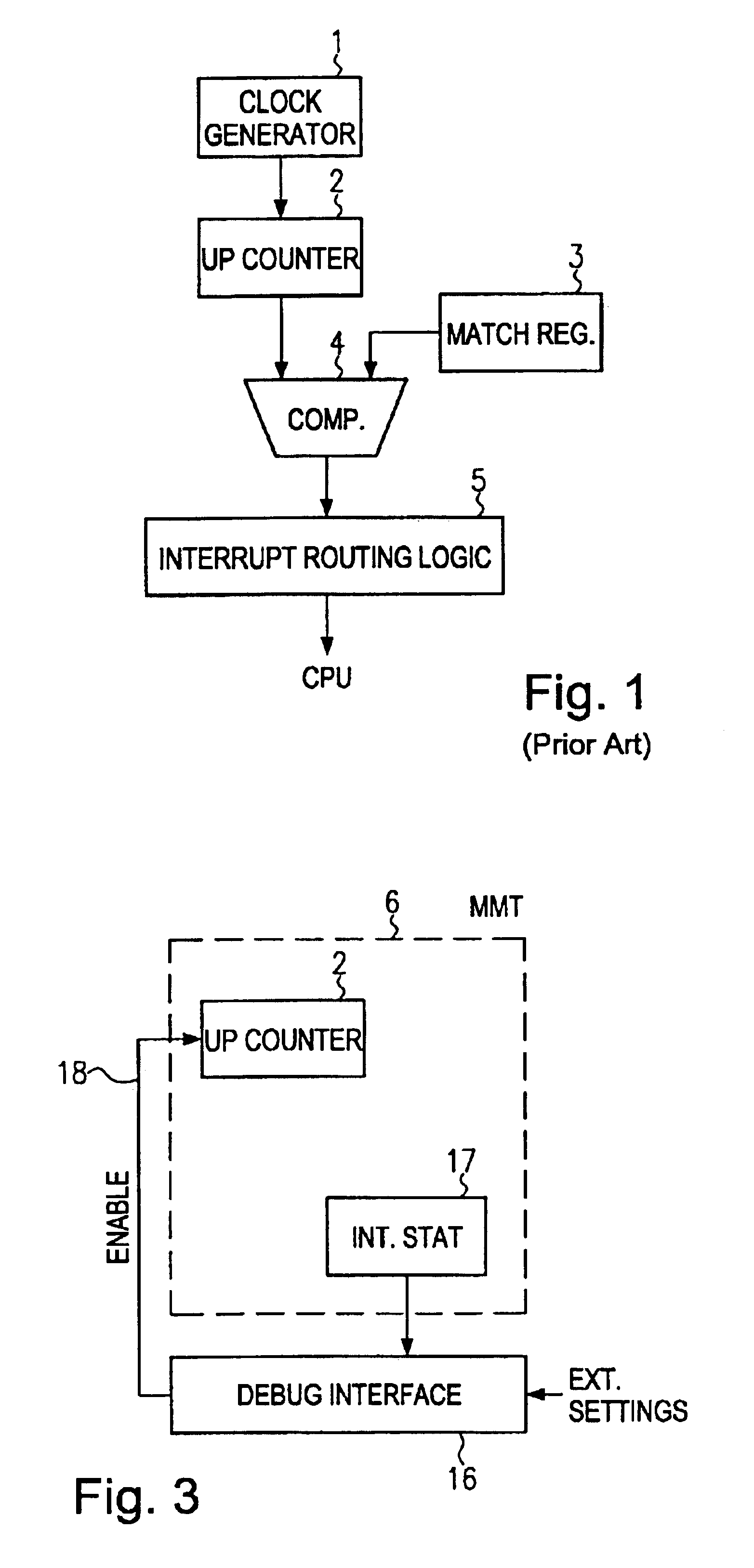
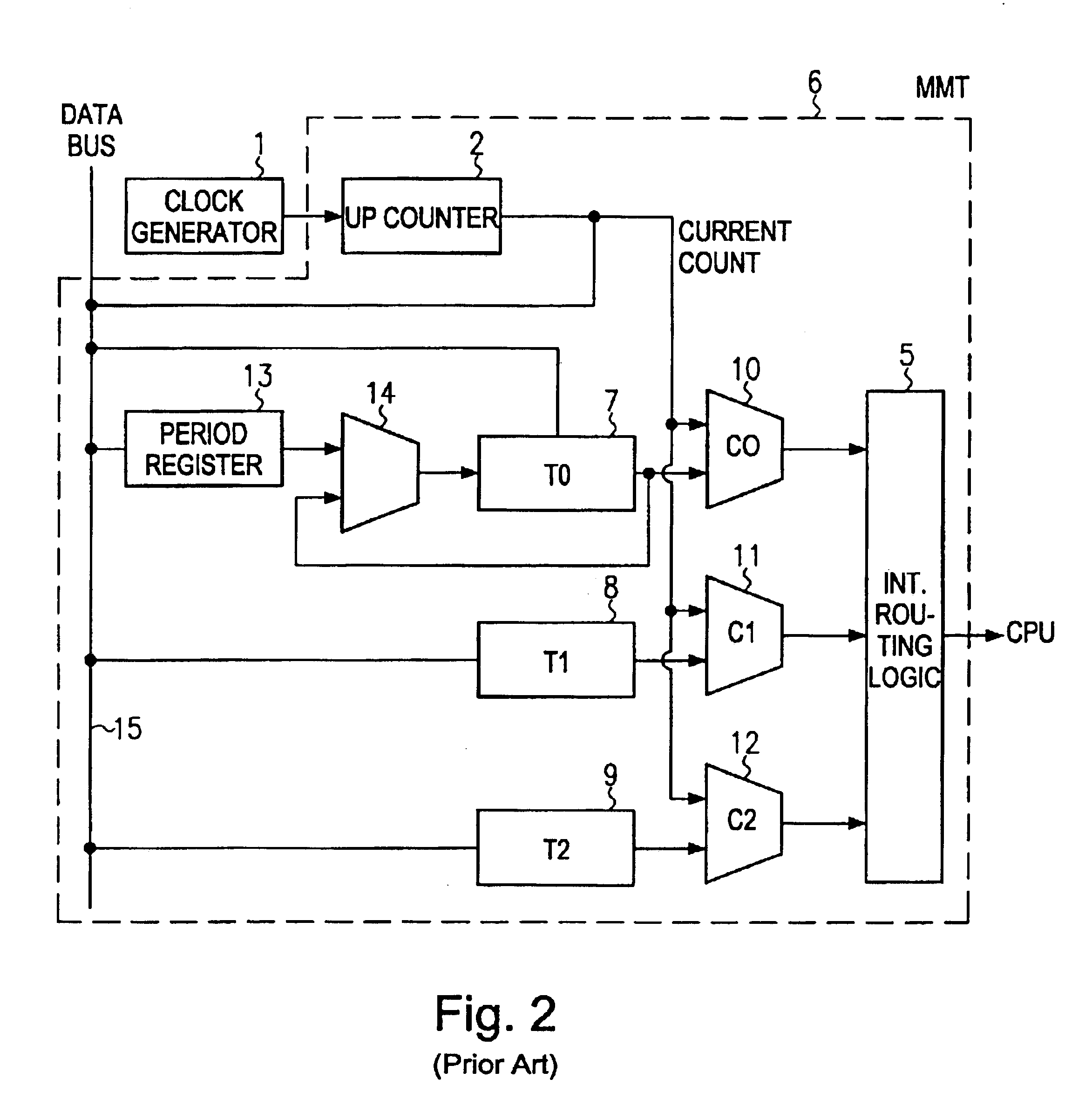
Referring to the drawings and in particular to FIG. 3, which illustrates a debug interface connected to an event timer. The configuration of FIG. 3 shows those components of an event timer, in particular the event timer (MMT) 6 as described with reference to FIG. 2, which interact with a debug interface as described herein. The debug interface 16 of the present invention monitors internal states of the event timer 6. The debug interface 16 generates an enable signal 18 for controlling the operation of the up-counter 2 in the event timer 6 based on a pre-defined relationship between the monitored internal state of the event timer and the enable signal 18. Preferably, the internal states of the event timer 6, e.g. interrupts generated by the event timer, are stored in a register 17 which may be read by the debug interface 16.
Due to the functionality built into the debug interf...
PUM
 Abstract
Description
Claims
Application Information
 - R&D Engineer
- R&D Manager
- IP Professional
- Industry Leading Data Capabilities
- Powerful AI technology
- Patent DNA Extraction
Browse by: Latest US Patents, China's latest patents, Technical Efficacy Thesaurus, Application Domain, Technology Topic, Popular Technical Reports.
© 2024 PatSnap. All rights reserved.Legal|Privacy policy|Modern Slavery Act Transparency Statement|Sitemap|About US| Contact US: help@patsnap.com


