
Disk drive including electrical traces integrally formed upon disk drive housing

a disk drive and electrical traces technology, applied in the direction of casings/cabinets/drawers, instruments, casings/cabinets/drawers, etc., can solve the problems of reducing the form factor of such disk drives, affecting the installation or assembly process, and affecting the effect of installation or assembly

Inactive Publication Date: 2005-01-04
WESTERN DIGITAL TECH INC
View PDF3 Cites 50 Cited by
  • Summary
  • Abstract
  • Description
  • Claims
  • Application Information

AI Technical Summary

Problems solved by technology

Such interaction results in forces applied to the hub which tend to rotate the hub.
Reduction of such disk drive form factor has proven challenging.
This is because the mere reduction of the size of the various disk drive components may result in such components being unable to conform to required specifications and standard form factors for such components, and may result in installation or assembly difficulties.

Method used


Image

  • Disk drive including electrical traces integrally formed upon disk drive housing
  • Disk drive including electrical traces integrally formed upon disk drive housing
  • Disk drive including electrical traces integrally formed upon disk drive housing

Examples


Embodiment Construction

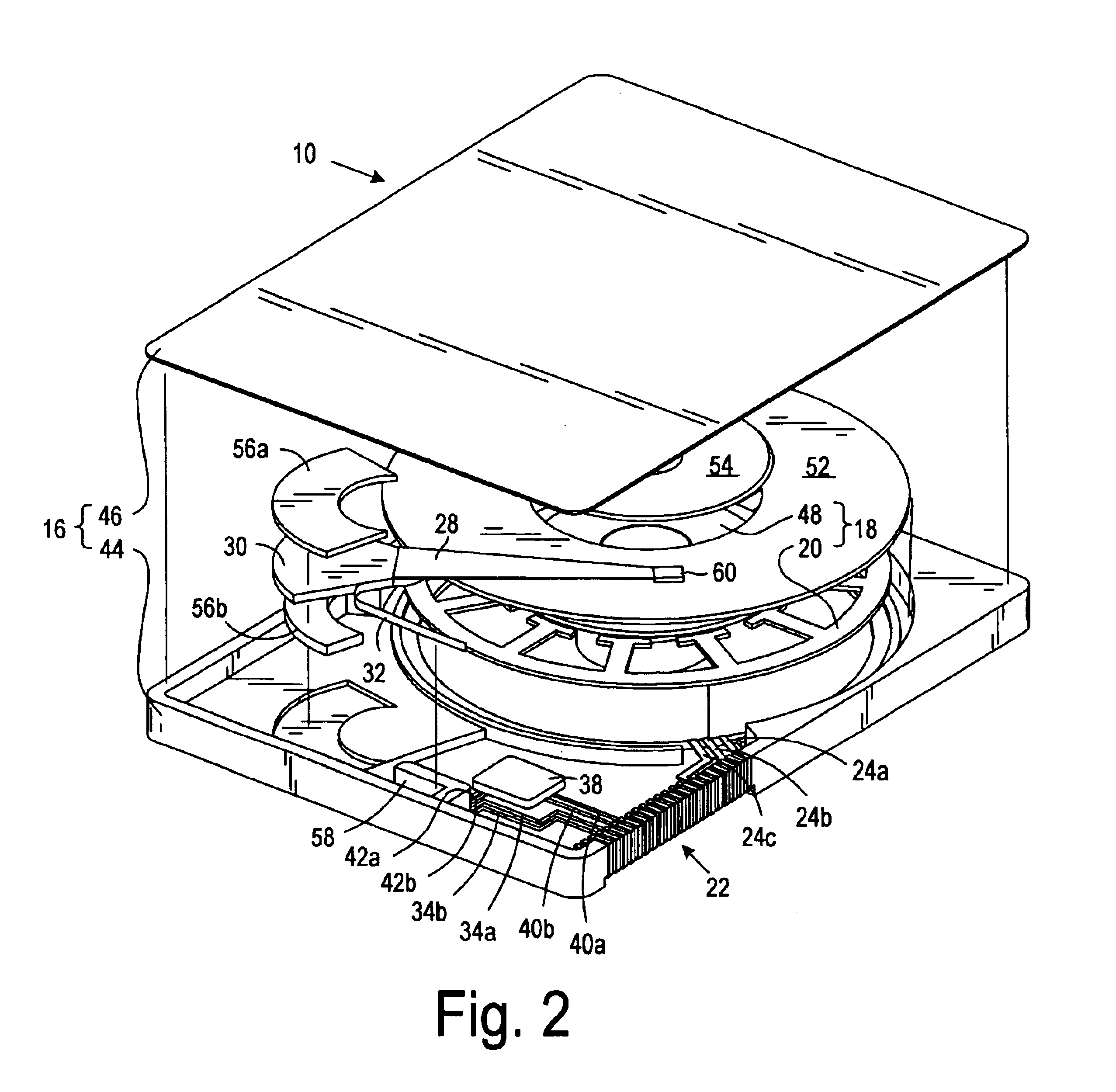
Referring now to the drawings wherein the showings are for purposes of illustrating preferred embodiments of the present invention only, and not for purposes of limiting the same, FIGS. 1-8 illustrate disk drives in accordance with the aspects of the present invention.

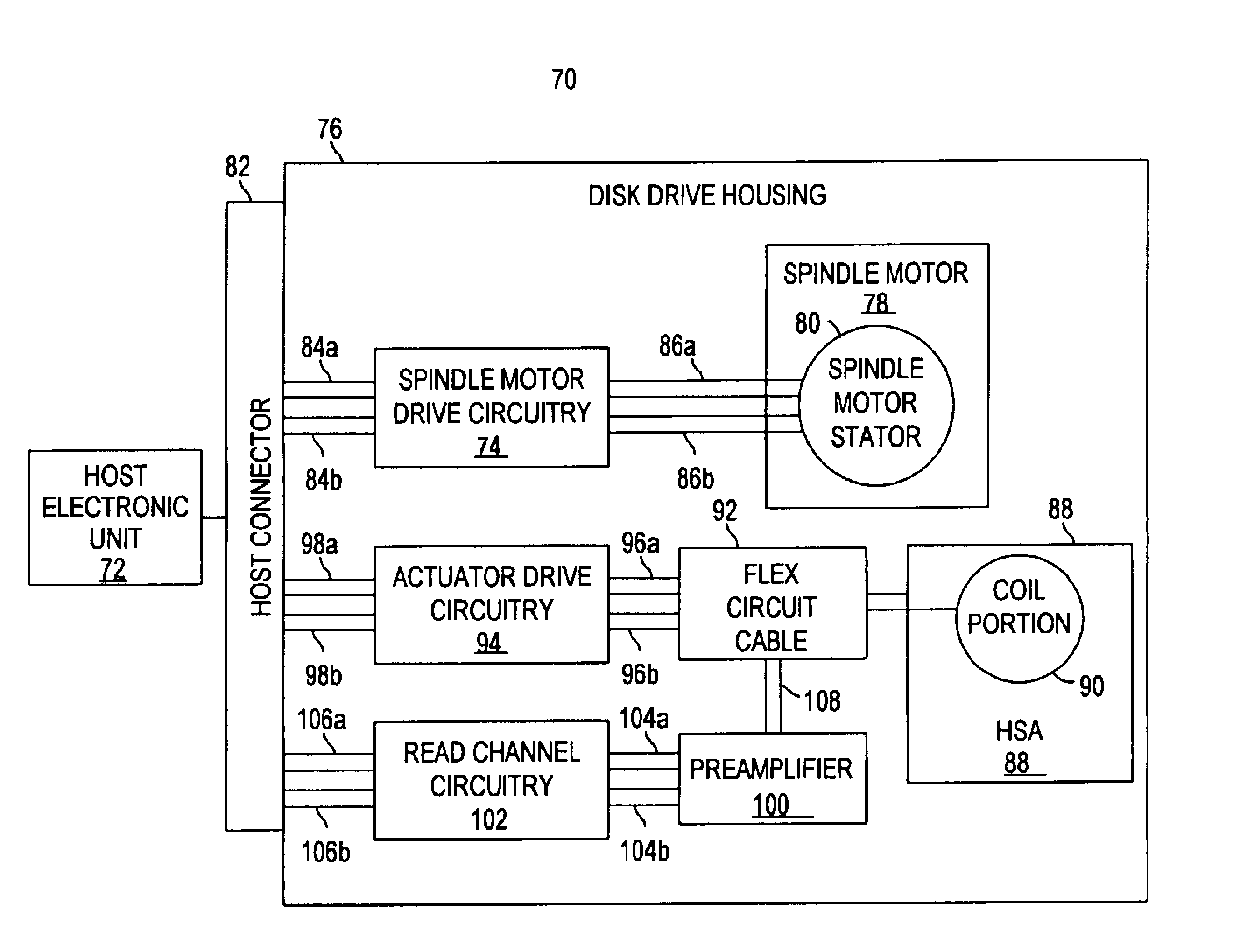
Referring now to FIG. 1 there is depicted a block diagram of a disk drive 10 in accordance with an aspect of the present invention as shown with host electronic unit 12. The host electronic unit 12 includes spindle motor drive circuitry 14. According to an aspect of the present invention, the disk drive 10 includes a disk drive housing 16, and a spindle motor 18 rotatably attached to the disk drive housing 16. The spindle motor 18 includes a stator 20. The disk drive 10 further includes a host connector 22 attached to the disk drive housing 16 which is operably connectable to the spindle motor drive circuitry 14 for receiving electrical signals from the spindle motor drive circuitry 14 for controlling the spindle motor...


PUM

PropertyMeasurementUnit
electricalaaaaaaaaaa
magnetic fieldaaaaaaaaaa
forcesaaaaaaaaaa

Abstract

A disk drive for use with a host electronic unit including spindle motor drive circuitry. The disk drive includes a disk drive housing, and a spindle motor rotatably attached to the disk drive housing. The spindle motor includes a stator. The disk drive further includes a host connector attached to the disk drive housing which is operably connectable to the spindle motor drive circuitry for receiving electrical signals from the spindle motor drive circuitry for controlling the spindle motor. The disk drive further includes a stator electrical trace integrally formed upon the disk drive housing from the stator to the host connector for electrically connecting the stator and the host connector.

Description

BACKGROUND OF THE INVENTION1. Field of the InventionThe present invention relates generally to disk drives, and more particularly to a disk drive having electrical traces formed upon a disk drive housing.2. Description of the Prior ArtThe typical hard disk drive includes a disk drive base, and a head disk assembly (HDA) and a printed circuit board assembly (PCBA) attached to the disk drive base. The head disk assembly includes at least one magnetic disk, a spindle motor for rotating the disk, and a head stack assembly (HSA) that includes at least one transducer head, typically several, for reading and writing data to and from the disk. As discussed further below, the printed circuit board includes functional portions of which may be characterized as spindle motor drive circuitry, actuator drive circuitry, and read channel circuitry.The head stack assembly includes an actuator assembly, at least one head gimbal assembly, and a flex circuit cable assembly. A conventional “rotary” or “...

Claims


Application Information

Patent Timeline
Patent Type & Authority Patents(United States)
IPC IPC(8): G11B19/20G11B33/12G11B5/48H05K1/00
CPCG11B5/4846G11B19/20G11B33/122G11B33/121H05K1/0284
Inventor ALEXANDER, JR., MCMAHAN COYLEGARRETT, WILLIAM W.
Owner WESTERN DIGITAL TECH INC
Learn More