
Pressure support system having a two-piece assembly

a pressure support and two-piece technology, applied in the direction of valve housings, valve operating means/releasing devices, functional valve types, etc., can solve the problems of a large amount of time, high cost, and the possibility of leakage of conventional pressure support devices

Inactive Publication Date: 2005-01-04
RIC INVESTMENTS LLC
View PDF22 Cites 118 Cited by
  • Summary
  • Abstract
  • Description
  • Claims
  • Application Information

AI Technical Summary

Benefits of technology

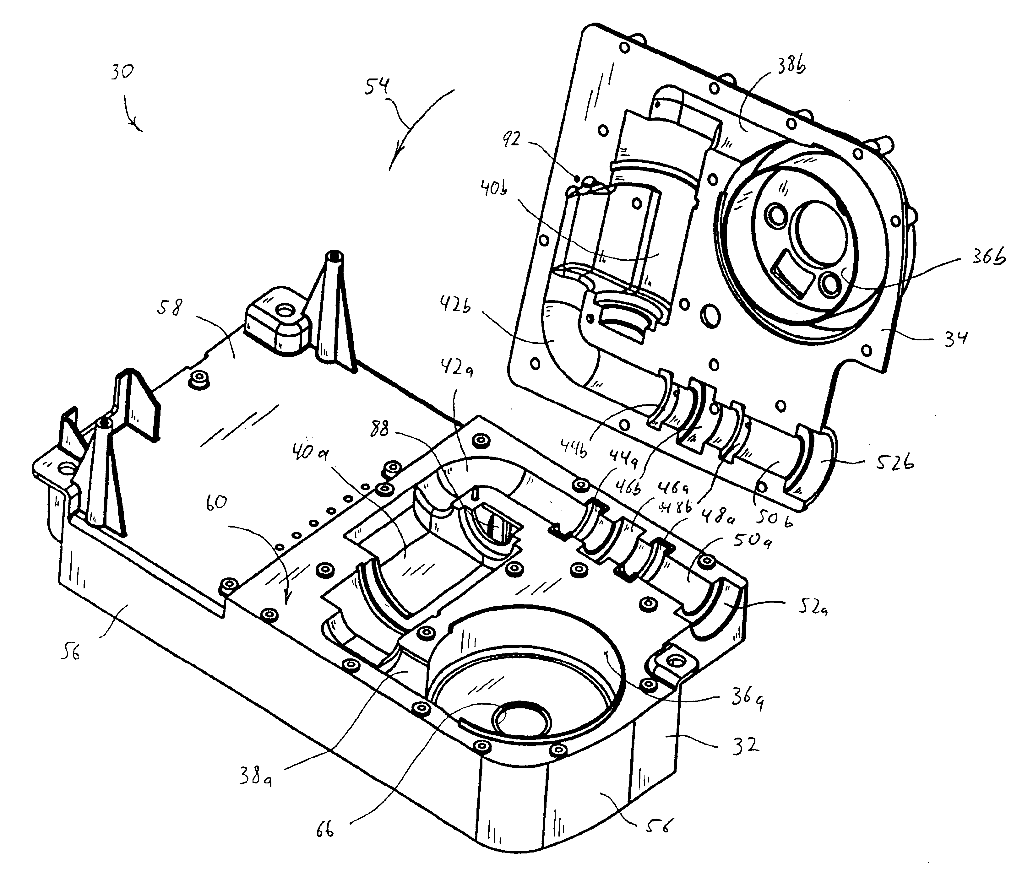
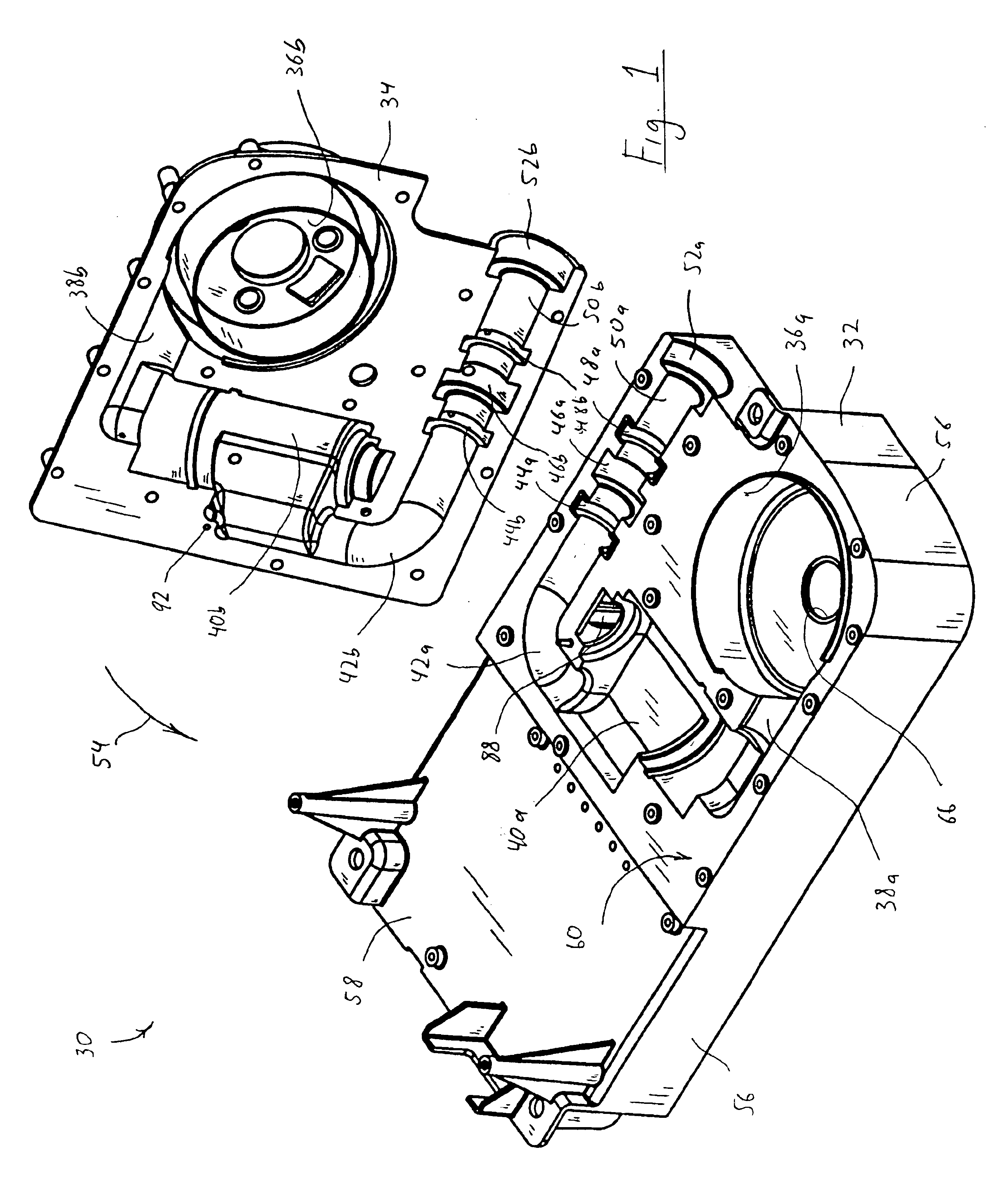
Accordingly, it is an object of the present invention to provide a pressure support system that overcomes the shortcomings of conventional pressure support systems. This object is achieved according to one embodiment of the present invention by providing a pressure support system that includes a first housing member having a first plurality of cavities defined therein and a second housing member having a second plurality of cavities defined therein. When assembled, the first and second plurality of cavities cooperate with one another to define at least one chamber that receives a component of the pressure support system, such as the pressure generator, pressure control assembly, or flow element. When assembled, the first and second plurality of cavities also cooperate with one another to define at least one conduit connected to such a component to communicate gas therewith. A fastening system secures the first and second housing members in the assembled relation. Thus, the present invention avoids the need for assembling the various components of the pressure support system to one another using conduits and conduit attaching elements.

Problems solved by technology

It can be appreciated that manufacturing a conventional pressure support device is relatively complicated and time consuming.
In addition, there is always a chance for leaks where the flexible tube attaches to the pressure generator, pressure control assembly, flow element, or the second external coupling on the pressure support system housing.

Method used


Image

  • Pressure support system having a two-piece assembly
  • Pressure support system having a two-piece assembly
  • Pressure support system having a two-piece assembly

Examples


Embodiment Construction

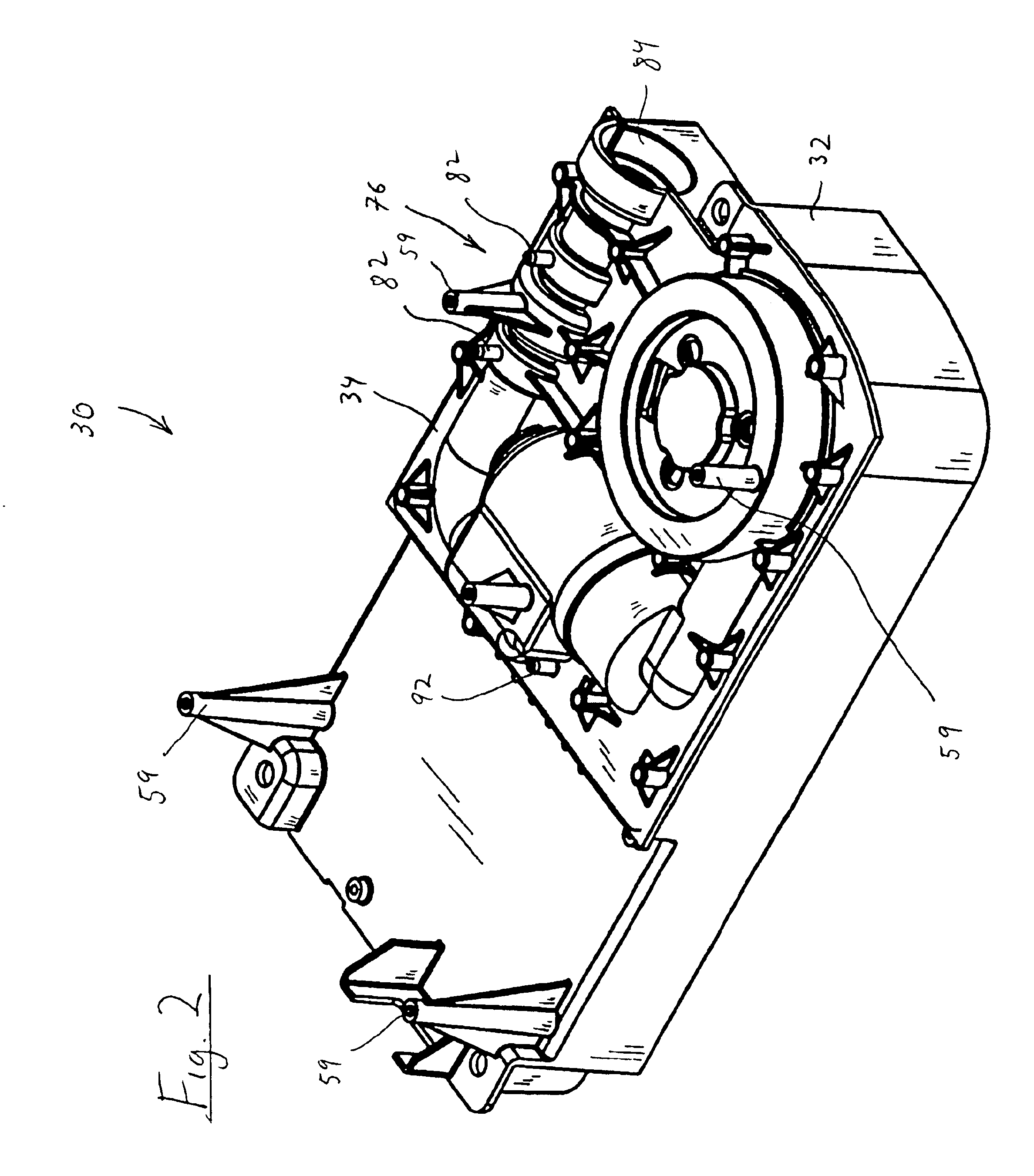
FIGS. 1 and 2 are perspective views of a pressure support system 30 according to the principles of the present invention. Pressure support system 30 includes a first housing member 32 and a second housing member 34, which are shown in an unassembled configuration in FIG. 1 and in an assembled configuration in FIG. 2. In an exemplary embodiment of the present invention, first and second housing members 32 and 34 are each defined by a unitary piece of material, such as an injection molded plastic. It is to be understood, that the present invention contemplates other techniques for forming the first and second housing members, such as thermoforming, casting, machining or any other conventional fabrication techniques. It is to be further understood, that the first and second housing member can each be formed from separate pieces of material that are bonded together. In addition, the first and second housing members can be formed from any material suitable for use in pressure support sys...


PUM


Abstract

A pressure support system that includes a first housing member and a second housing member. The first housing member has a first plurality of cavities defined therein, and the second housing member has a second plurality of cavities defined therein. The first and second plurality of cavities cooperate to define (a) a first chamber adapted to receive a first component of the pressure support system, (b) a second chamber adapted to receive a second component of the pressure support system, and (c) a first conduit connecting the first component and the second in fluid communication when the first and second housing members are assembled. A fastening system secures the first and second housing members in an assembled relation.

Description

BACKGROUND OF THE INVENTION1. Field of the InventionThe present invention pertains to a pressure support system, and, in particular, to a pressure support system having a two-piece assembly that houses at least one component of the pressure support system and that defines at least one fluid connection for carrying gas to or from this component.2. Description of the Related ArtPressure support systems that provide a flow of gas to an airway of a patient at an elevated pressure via a patient circuit to treat a medical disorder are well known. For example, it is known to use a continuous positive airway pressure (CPAP) device to supply a constant positive pressure to the airway of a patient to treat obstructive sleep apnea (OSA). It is also known to provide a positive pressure therapy in which the pressure of gas delivered to the patient varies or is synchronized with the patient's breathing cycle or with the patient's respiratory effort to maximize the therapeutic affect and comfort t...

Claims


Application Information

Patent Timeline
IPC IPC(8): A61M16/00
CPCA61M16/0057A61M2205/42A61M16/0066A61M16/0069A61M2016/0027A61M16/0858Y10T137/7761Y10T137/598Y10T137/599Y10T137/776
Inventor KUEHN, DANIEL
Owner RIC INVESTMENTS LLC
Learn More