
Reconfiguration method applicable to an array of identical functional elements

a functional element and array technology, applied in the field of reconfiguration methods applicable to arrays of identical functional elements, can solve the problems of poor manufacturing output, complex software used, and increasing complexity of the computer both in terms of elements

Inactive Publication Date: 2004-11-30
COMMISSARIAT A LENERGIE ATOMIQUE ET AUX ENERGIES ALTERNATIVES
View PDF3 Cites 24 Cited by
  • Summary
  • Abstract
  • Description
  • Claims
  • Application Information

AI Technical Summary

Problems solved by technology

The increasing possibilities of micro-electronic technology, as well as the evolution of multiprocessor architectures, are leading to computers that are more and more complex both in terms of elements composing them (electronic gates, memories, registers, processors, .
. . ) and in terms of complexity of the software used.
1 Machines having a parallel or extensively parallel structure are subject to faults due to the very great number of processors and their complexity, leading to poor manufacturing output and serious faults under normal operation.
In such systems, the main disadvantage is that of limited bandwidth, i.e. the amount of information that can be put through.
Performance loss is then limited.
On the contrary, the spare processors are very poorly used as one line is required to tolerate one fault, and in case of a faulty bypass, the whole system is down.
it is not suitable for unidirectional links; indeed, in this case, two connection buses, one round trip, are required for connecting the considered processor to each of its neighbours.
the number of switching elements passed between two logically neighbouring processors is not deterministic, which makes the method ineffective for dealing with the case of synchronous interprocessor communications.
highly limiting inoperative communication media of the network;

Method used


Image

  • Reconfiguration method applicable to an array of identical functional elements
  • Reconfiguration method applicable to an array of identical functional elements
  • Reconfiguration method applicable to an array of identical functional elements

Examples


Embodiment Construction

This invention relates to a method for reconfiguring a network of identical functional elements.

Reconfiguration Method

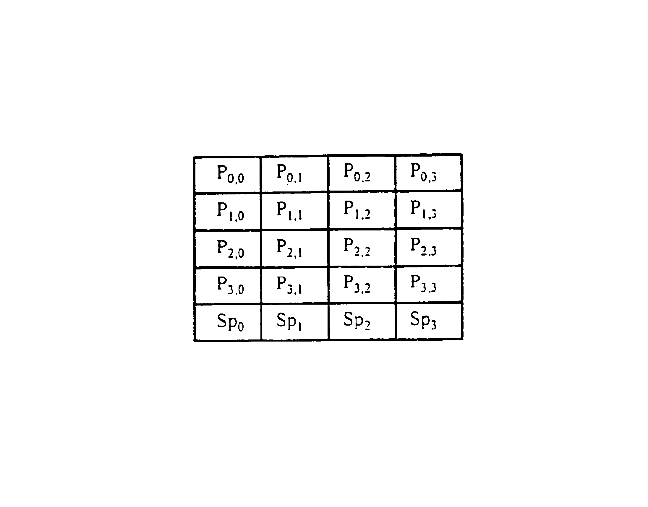
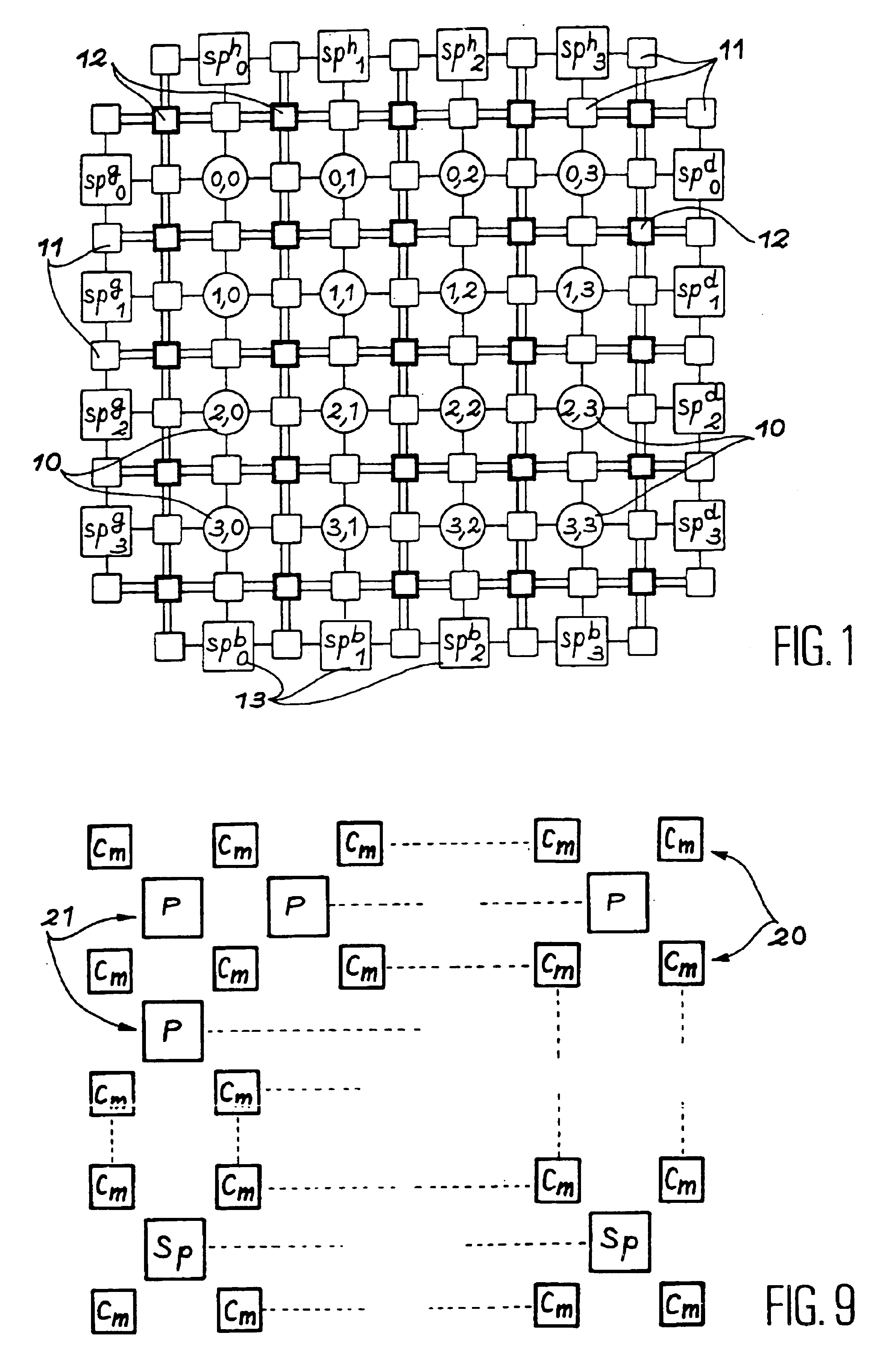
In the "m-Track, n-Spare" structure of the known art, illustrated in FIG. 1, the reconfiguration method consists in searching for a track called "compensation track" to replace a faulty elementary functional element with a spare functional element. Then, starting with this faulty elementary functional element, each functional element is replaced with the next functional element available, the nearest one on the track. However, this method is really efficient only when there are spare functional elements in at least one line and one column, which is not possible with one line of spare functional elements and two unidirectional tracks. Also, such a method does not allow the number of switches in the communication tracks to be reduced.

On the other hand, the reconfiguration method of the invention is based on a positioning technique not correlated with routing.

Positionin...


PUM


Abstract

This invention relates to a method for reconfiguring a network of parallel functional elements tolerant to the faults of these functional elements including said basic functional elements (P), spare functional elements (Sp), interconnecting elements (Cm) of these functional elements and a control unit, said method comprising:a step of positioning the functional elements of the logic network on the physical network;a routing step of programming interconnecting elements on the physical network, by choosing a maximum number of interconnecting elements which can be passed between two neighbouring processors using a shortest track search algorithm.

Description

This invention relates to a reconfiguration method applicable to a network of identical functional elements.The field of the invention is in particular that of parallel computers composing a unit of matrix, ring, or hypercube interconnected processors, and that of 1D or 2D correlators, matrix architectures of blocks computing the fast Fourier transform (FFT). Two examples of the first kind of applications are thus given in the document referenced as [1] at the end of the description.PRIOR ARTThe increasing possibilities of micro-electronic technology, as well as the evolution of multiprocessor architectures, are leading to computers that are more and more complex both in terms of elements composing them (electronic gates, memories, registers, processors, . . . ) and in terms of complexity of the software used.The designers of such computers having a high integration parallel or extensively parallel structure must take into account two conflicting requirements:1 Machines having a par...

Claims


Application Information

Patent Timeline
IPC IPC(8): G06F15/173G06F15/16
CPCG06F15/17343
Inventor CLERMIDY, FABIENCOLLETTE, THIERRY
Owner COMMISSARIAT A LENERGIE ATOMIQUE ET AUX ENERGIES ALTERNATIVES
Learn More