Toilet unit for a vehicle, in particular a rail vehicle

a technology for rail vehicles and toilets, applied in the field of toilet units for vehicles, can solve the problems of complicated installation, limited headroom of toilets, and toilet units also suffer from drawbacks, and achieve the effect of reducing the ergonomically usable space inside the cubicl

Inactive Publication Date: 2004-11-30
ALSTOM SA
View PDF7 Cites 2 Cited by
  • Summary
  • Abstract
  • Description
  • Claims
  • Application Information

AI Technical Summary

Benefits of technology

Thus, an object of the present invention is to remedy these drawbacks by proposing a toilet unit of optimized configuration that incorporates all of the equipment necessary for it to operate, without significantly reducing the ergonomically usable space inside the cubicle.

Problems solved by technology

Such a configuration with tanks separate and remote from the toilet unit suffers from the drawbacks of complicating installation of the toilet unit by requiring numerous connections, and also of requiring space on the vehicle underframe for the tanks.
Such a toilet unit offers the advantage of having tanks that do not occupy space on the vehicle underframe, but it suffers from the drawback of requiring walls whose structure is sufficiently rigid to be capable of supporting the clean water tank which, because of its situation, is of small capacity and therefore connected to a water feed circuit of the train, making it complicated to install.
Such a toilet unit also suffers from the drawback of having a cubicle whose headroom is limited by the size of the clean water tank.
Finally, the configuration of such a toilet unit is such that, for a given limiting volume for the toilet unit, the waste water retention tank installed in one of the walls reduces the usable width of the cubicle accordingly.

Method used


Image

  • Toilet unit for a vehicle, in particular a rail vehicle
  • Toilet unit for a vehicle, in particular a rail vehicle
  • Toilet unit for a vehicle, in particular a rail vehicle

Examples


Embodiment Construction

To make the drawings clearer, only those elements which are necessary to understand the invention are shown.

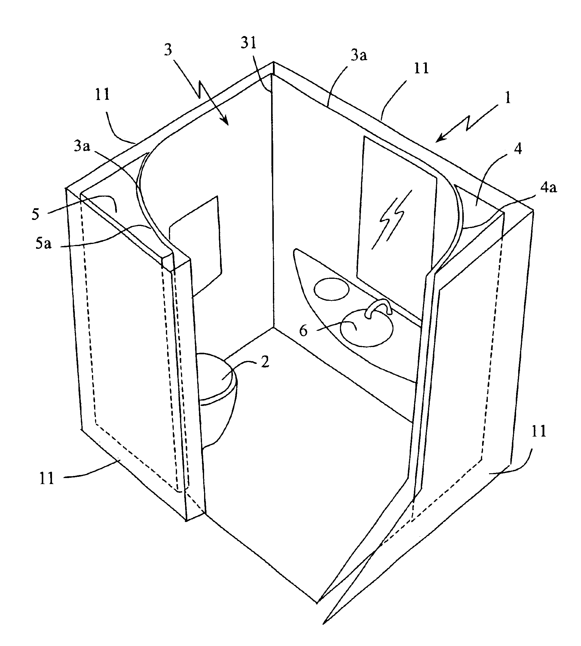
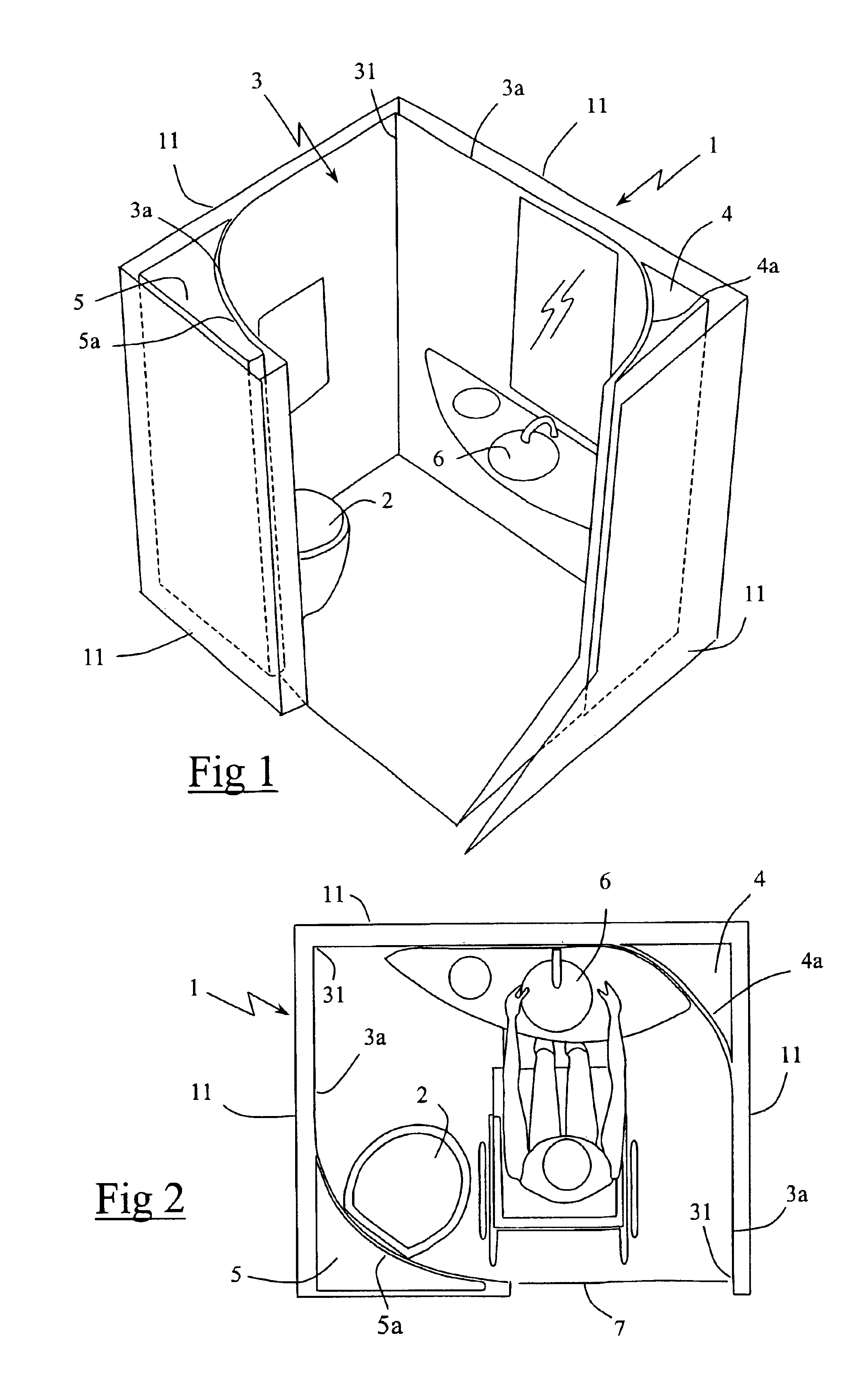
FIG. 1 shows a toilet unit designed to be installed in a rail vehicle. As shown in this figure, the toilet unit is designed to occupy a limiting outside volume 1 that is in the shape of a rectangular block, and that is defined by a set of side walls 11, this limiting volume being suitable for being received in a space provided in the rail vehicle for this purpose. Inside the limiting volume 1, the toilet unit comprises a cubicle 3 defined by two inner partitions 3a of arcuate shape, these inner partitions 3 being set back a little from the side walls 11 defining the limiting volume 1.

The inner partitions 3a are assembled together along two vertical edges 31 disposed in the vicinities of respective ones of two opposite corners of the rectangular limiting volume 1. In the vicinity of the respective edge 31, each inner partition 3a extends parallel to the adjacent side wall 11. O...


PUM


Abstract

A toilet unit for a vehicle, in particular a rail vehicle, the toilet unit comprising a cubicle equipped at least with a toilet pan or with a handbasin, said toilet unit defining a limiting volume that is in the shape of a rectangular block, and that is suitable for fitting into a space provided in the rail vehicle for this purpose, said toilet unit incorporating, inside said limiting volume, at least a clean water tank and a waste water retention tank, wherein said clean water tank and said waste water retention tank are disposed vertically in respective corners of the rectangular limiting volume, each tank having an outside wall that is wedge shaped to match the shape of the corner of the rectangular limiting volume, and an inside wall on its side that faces into the cubicle that substantially matches the shape of said cubicle.

Description

It is common to equip rail vehicles with toilet units, each such unit comprising a cubicle provided with equipment such as a toilet pan or a handbasin. Such toilet units are usually connected to tanks for clean water and for waste water retention disposed under the frame of the vehicle. Such a configuration with tanks separate and remote from the toilet unit suffers from the drawbacks of complicating installation of the toilet unit by requiring numerous connections, and also of requiring space on the vehicle underframe for the tanks.U.S. Pat. No. 6,101,766 discloses a toilet unit incorporating a waste water retention tank in one of its side walls, and having a ceiling supporting a clean water tank. Such a toilet unit offers the advantage of having tanks that do not occupy space on the vehicle underframe, but it suffers from the drawback of requiring walls whose structure is sufficiently rigid to be capable of supporting the clean water tank which, because of its situation, is of sma...

Claims


Application Information

Patent Timeline
Patent Type & Authority Patents(United States)
IPC IPC(8): A47K4/00B61D35/00B63B29/14B60R15/00B63B29/00B60R15/02B60R15/04A47K17/00
CPCA47K4/00B60R15/00B63B29/14B60R15/04B61D35/00B60R15/02
Inventor LECLERCQ, BERNARDRENAUD, BERNARD
Owner ALSTOM SA
Why Eureka
Try Eureka